• There were many reasons for the change of the site software, the biggest was security. The age of the old software also meant no server updates for certain programs. There are many benefits to the new software, one of the biggest is the mobile functionality. Ill fix up some stuff in the coming days, we'll also try to get some of the old addons back or the data imported back into the site like the garage. To create a thread or to reply with a post is basically the same as it was in the prior software. The default style of the site is light colored, but i temporarily added a darker colored style, to change you can find a link at the bottom of the site.

DIY laser alignment - correcting dealer foul up

I've separated this post from the previous one because it addresses the issue of aligning the front wheels to the rear wheel rather than aligning to the chassis centre line.

Since when running along the road your rear wheel will steer the bike until the rear wheel is running in the direction of travel it makes little difference to the bike which datum you use when setting your toe measurement.

The only difference, if BUDS is used to set the steering after the toe is set, is in the angle of the handlebars and the steering arm.

If your rear wheel happened to be perfectly in line with the chassis, as it should ideally be, then there will be no rear wheel steering at all. However, road camber will run the bike down hill on the camber so in practise there will likely always be some misalignment.

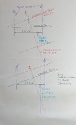
Note from the drawings below how the bike is guaranteed to be running slightly sideways if the rear wheel is not parallel to the chassis.
Obviously, in the drawing, rear wheel misalignment is exaggerated to clearly show the effect it has on the chassis angle.
 

Attachments

  • 20210317_155107.jpg
    20210317_155107.jpg
    17.1 KB · Views: 24
The only difference, if BUDS is used to set the steering after the toe is set, is in the angle of the handlebars and the steering arm.

If your rear wheel happened to be perfectly in line with the chassis, as it should ideally be, then there will be no rear wheel steering at all. However, road camber will run the bike down hill on the camber so in practise there will likely always be some misalignment.
Correct. In his video about laser alignment Lamont says, as has Joe Meyer also, it's important to check the rear belt tracking. I'm sure this is based on the assumption that the engine and transmission will be in line with the chassis so the tire will also be in alignment if the belt tracks properly.
 
I had a look at your previous photos.

In one of them, the laser was mounted above the axle, and in the other it was below the axle. While that should not be critical, it is important that each laser is absolutely level when projecting to the targets.

FWIW, be very aware of the accuracy and tolerances. With suggested total toe of 1”, that equates to 1/4” per target. An error of 1/16” is a misalignment of 25%.

It's good to see another DIY approach! Well done you.

However, it's essential that the laser beams are parallel to the floor. If they are not, any variation in wheel camber will affect the convergence of the beam. It's also essential because any misalignment of the wheels will be subject to some caster and since toe-in is misalignment it will affect your outcome.

If you're using distance measurements you need to settle on a datum for that measurement, BRP stipulates the toe in degrees so gives no basis for measurement. I use the wheel rim diameter since it's easy and repeatable.

Thanks for the kind words. We need to keep in mind that the alignment process is not an exercise in "exactitude", but rather one of "close enough". Owner experience has demonstrated that a toe-in of about 1" over 76" fore and aft gives a good steering experience. My toe-in this past year was only about 1/2" and my RT tracked rather well. Lamont, in his video, discusses 1" to 1 1/4" so that affirms that toe-in setting does not have to be exact. With this in mind PMK, I would argue that the laser does not have to be exactly level, but should be close. But your comment made me think about the influence of camber. I then I read Pink's comment about it, so I decided to see just how much of a factor it really is. As you can see in these two pics it's not much. I put one laser at the top of the disk and the other at the bottom.

Left camber check.jpg

Right camber check.jpg

I was thinking of using a correction factor for the forward and rearward beam spreads, but I think I will just attach the levels at the lower part of the brake disk. PMK, what you saw was one laser being used for forward and rearward projections. The HF level magnets weren't strong enough to keep them secure so I put a screw into them through the disk and then rotated the disk. I had completely forgotten about camber. The magnets on the Johnson lasers are much stronger so I think pulling, rotating, and replacing them will work OK.

As for Pink's comment about being parallel to the floor the requirement is more like the laser needs to perpendicular to the vertical axis of the camber. But here also, close is good enough since we don't know exactly what that vertical axis is. And then there is the influence of caster. So nothing about wheel alignment is exact, just close!

Well, I need to get ready to get my second Covid shot so I'll get back to this later.
 
One of the most important things when you're doing this is your targets being set up perfectly on parallel squared lines. I bought the dealer set up which is not affordable to most people. It will never pay for itself. I've always done everything myself. They're a lot of good videos on it even if you're not using the factory system great explanations of how it gets done. The principal is the same. Mine is 150 inch by 75 inch rectangle with the front hubs centered at 75 in. Sean smokes and lamonster have both shown this system on YouTube videos true laser track is the system.
 

Attachments

  • IMG_20210317_155954106.jpg
    IMG_20210317_155954106.jpg
    69.2 KB · Views: 30
  • IMG_20210317_155949344.jpg
    IMG_20210317_155949344.jpg
    57.7 KB · Views: 25
So nothing about wheel alignment is exact, just close!

:agree: It's easy to get into all the variances especially if you have precision instruments like the Rolo gear but my shadetree experience is as long as it eliminates all the wandering,shakes, pulling one way or the other and evens out tyre wear you have mission accomplished.
No two roads are the same, different weights, tyres, riding styles, ambient temperatures, wet/dry all have small input to the total outcome but we don't chase that fine a line for everyday use.
I've tried different settings and couldn't tell the difference (perhaps my backside is tone deaf :thumbup:) unlike the first alignment which was immediately noticeable to me and my passenger.
 
One of the most important things when you're doing this is your targets being set up perfectly on parallel squared lines. I bought the dealer set up which is not affordable to most people. It will never pay for itself. I've always done everything myself. They're a lot of good videos on it even if you're not using the factory system great explanations of how it gets done. The principal is the same. Mine is 150 inch by 75 inch rectangle with the front hubs centered at 75 in. Sean smokes and lamonster have both shown this system on YouTube videos true laser track is the system.

OK, now how about camber influence on track width? Lamont just turns the laser down and plumb, fore and aft. He doesn't address how much the track width is impacted by camber. Does the Rolo system equipment or instructions address that? Obviously, if the wheels have a negative camber the laser dots on the floor are going to be closer together than if they were at the center of the wheel.

I'm on my to the garage to see if I can handle on that source of variation.
 
Correct. In his video about laser alignment Lamont says, as has Joe Meyer also, it's important to check the rear belt tracking. I'm sure this is based on the assumption that the engine and transmission will be in line with the chassis so the tire will also be in alignment if the belt tracks properly.

A wonderful assumption, but does play into the concept of not needing exact or precise.
 
OK, now how about camber influence on track width? Lamont just turns the laser down and plumb, fore and aft. He doesn't address how much the track width is impacted by camber. Does the Rolo system equipment or instructions address that? Obviously, if the wheels have a negative camber the laser dots on the floor are going to be closer together than if they were at the center of the wheel.

I'm on my to the garage to see if I can handle on that source of variation.

I believe you have already answered your own question. You posted images indicating the beams essentially strike the vertical level with minimal deviation. Therefore, your current camber is demonstrating to be very close to 0.0*.
 
Well, I got it finished today. I opted to not make any adjustment for camber as it was just not enough to have a significant effect on the end result. Since I was going to be adjusting both tie rods to get the crabbing out I didn't want to mess with constantly resetting the handlebar position. I tied it down as you can see here. Keeping the handlebar steady wouldn't have been a problem, maybe, if I would have done the alignment with the tires on!

Handlebar Tie down.jpg

I set the targets in the rear 28 5/16" from the tire center with an additional target line 5/16" outside of the track width. The track width was 56 5/8". I kept the laser level at the bottom of the brake rotor disk, flipping it over to shine to the front. I set the front targets to the beams and measured the beam spread. It was right on 56" which gave me a toe-in right at 1 1/4" over 160" front rear to front. I declared that good enough so I tightened the tie rods and then used BUDS to reset the steering angle sensor and torque offset. After I put the tires back on I rolled the bike back and forth and rechecked the SAS and torque offset. The SAS changed about half a degree so I reset it again.

I then went for a ride of several miles. It could be my imagination but I think it tracked and handled better than it ever has, and I think just as good as it did after I put the Contis on front after Squared Away aligned it! Hands off tracking looks like it is good but I didn't have enough level smooth road to know for certain. When I got home I rode it straight into the garage. The handlebar was square to the bike. The SAS changed to about .75° so I zeroed it again. The torque offset had changed to about -5 which I think was caused by my tight turns in a parking lot checking to see if right and left turn radiuses were the same. I zeroed it again. Tomorrow I'm going for a 160 mile ride with the GW chapter I still belong to. I'll check the SAS and torque offset after that to see how much, if any, they change.

One big conclusion I have come to is getting a steel plate that attaches to the rotor through the wheel spokes is the way to go. Doing all this with the tires off complicated things a fair amount, but I did get a real good understanding of all the angles and settings that are involved. Don't try to get by with cheap laser levels. The Harbor Freight ones I first tried using were near junk. The Johnsons I got worked plenty good enough but they are not the ultimate.

If you're going to do a lot of alignments, get the Rolo kit. All in all I'm quite pleased with the way it has all turned out. The service manual indicates the steering column sections are keyed for alignment, so the dealer techs got it put back together correctly. They just did a royal screw up on the alignment.
 
Gotta love a happy ending.Pisses me off the dealers won't even have a go at a setup like this if they can't justify buying Rolo.The lost sales because test rides on a wandering bag of crap putting newcomers off must be huge!
I just used a couple of straight edge inch square tubes strapped across the wheel spokes on my F3's to mount the lasers was easiest for me.
I settled on target spacings of 150 inches and 1-1/4'' toe so a smidgeon more toe than you used.
I have twisty bumpy roads here and suspension set on the firm side on my bike while the wifes F3 is stock apart from a sway bar and both are on rails by comparison to the factory guess.
Next tyre change I might double check the alignment but we're more than happy with my back yard hacker setup.
 
One of the most important things when you're doing this is your targets being set up perfectly on parallel squared lines. I bought the dealer set up which is not affordable to most people. It will never pay for itself. I've always done everything myself. They're a lot of good videos on it even if you're not using the factory system great explanations of how it gets done. The principal is the same. Mine is 150 inch by 75 inch rectangle with the front hubs centered at 75 in. Sean smokes and lamonster have both shown this system on YouTube videos true laser track is the system.

Just curious. Why are the lasers in the Rolo system pictured in the post labeled “left & right?” Shouldn’t they project accurately regardless of which side they are on? To the front or rear?
 
Just curious. Why are the lasers in the Rolo system pictured in the post labeled “left & right?” Shouldn’t they project accurately regardless of which side they are on? To the front or rear?

To maintain tighter tolerances and expected more accurate alignment, ROLO machines the adapter trays for each laser to match the laser level base and calibrates the lasers in house.
 
Well, I got it finished today. I opted to not make any adjustment for camber as it was just not enough to have a significant effect on the end result. Since I was going to be adjusting both tie rods to get the crabbing out I didn't want to mess with constantly resetting the handlebar position. I tied it down as you can see here. Keeping the handlebar steady wouldn't have been a problem, maybe, if I would have done the alignment with the tires on!

View attachment 188641

I set the targets in the rear 28 5/16" from the tire center with an additional target line 5/16" outside of the track width. The track width was 56 5/8". I kept the laser level at the bottom of the brake rotor disk, flipping it over to shine to the front. I set the front targets to the beams and measured the beam spread. It was right on 56" which gave me a toe-in right at 1 1/4" over 160" front rear to front. I declared that good enough so I tightened the tie rods and then used BUDS to reset the steering angle sensor and torque offset. After I put the tires back on I rolled the bike back and forth and rechecked the SAS and torque offset. The SAS changed about half a degree so I reset it again.

I then went for a ride of several miles. It could be my imagination but I think it tracked and handled better than it ever has, and I think just as good as it did after I put the Contis on front after Squared Away aligned it! Hands off tracking looks like it is good but I didn't have enough level smooth road to know for certain. When I got home I rode it straight into the garage. The handlebar was square to the bike. The SAS changed to about .75° so I zeroed it again. The torque offset had changed to about -5 which I think was caused by my tight turns in a parking lot checking to see if right and left turn radiuses were the same. I zeroed it again. Tomorrow I'm going for a 160 mile ride with the GW chapter I still belong to. I'll check the SAS and torque offset after that to see how much, if any, they change.

One big conclusion I have come to is getting a steel plate that attaches to the rotor through the wheel spokes is the way to go. Doing all this with the tires off complicated things a fair amount, but I did get a real good understanding of all the angles and settings that are involved. Don't try to get by with cheap laser levels. The Harbor Freight ones I first tried using were near junk. The Johnsons I got worked plenty good enough but they are not the ultimate.

If you're going to do a lot of alignments, get the Rolo kit. All in all I'm quite pleased with the way it has all turned out. The service manual indicates the steering column sections are keyed for alignment, so the dealer techs got it put back together correctly. They just did a royal screw up on the alignment.

Always cool to get good results from a DIY project. Since you had decided close enough is good enough, that allows the ability to lessen concerns getting base settings accurate.

One difference compared to typical alignments is how you determined track width. By using the brake disc, your track width is in error by the amount of existing toe in or toe out. Granted it should be a small amount, but is there. In theory, if you set each of targets to your baseline width determined from the track width you measured, quite possibly the wheels should have been aligned to 0.0” toe, the dimension of targets verified, then set the toe based off being absolutely trued.

I would also be curious to compare toe settings how you did them with weight on ball joints vs weight on wheels. I suspect, but may be incorrect that weight on wheels will add toe out. The setups I am familiar with that removes the wheels typically has precision struts that bolt onto the wheel studs and support the vehicle while allowing easy access for all adjustments. Toe, camber and caster. Since the Spyder has only adjustable toe, and easy access to making adjustments, that would be overkill.

All the best with you new alignment, be safe and enjoy.
 
Has anyone given any thought on a way to cure the bump steer problem caused by the large difference in length between the control arms and the tie rods.I know giving it a little extra toe in helps mask the problem but Im thinking maybe some kind of idler arm system like they use on most trucks would be the answer.I feel like a lot of folks use the stiffer shocks to keep the body roll to a minimum but that results in a rougher ride and I think the real answer is to fix the real problem which is bump steer.
 
Has anyone given any thought on a way to cure the bump steer problem caused by the large difference in length between the control arms and the tie rods.I know giving it a little extra toe in helps mask the problem but Im thinking maybe some kind of idler arm system like they use on most trucks would be the answer.I feel like a lot of folks use the stiffer shocks to keep the body roll to a minimum but that results in a rougher ride and I think the real answer is to fix the real problem which is bump steer.

Years ago I discussed making 4130 suspension arms with a friend. Plan was to design them with adjustable caster and camber. From race chassis setup, I know bump steer is undesirable. Unfortunately, the Spyders simple bellcrank style steering would require adding mounts and designing two idler arms, plus running shortened tie rods. A second alternative would be to remove the existing steering design and install a long rack type setup.

On a vehicle with less that 5” of wheel travel, and truthfully not on the pinnacle of performance, the true need to reduce or eliminate bump steer becomes a complicated expensive rework of the chassis and steering.

Yes, you are correct too in that reduced roll tendency lessens bump steer, and also some folks do wind upoversprung, suffering with a harsh ride. Chassis setup, beyond toe alignment is likely more than most owners understand or would persue.

:agree: ..... just about anything is possible if you want to spend the money needed to accomplish the task ....... Spyders handle well enough for the purpose intended. And :agree: ... you can " over-spring " them pretty easy because of their light-weight ..... I achieved better handling by leaving the OEM shocks with no pre-load dialed in , but I did change the upper mount for the shocks to give a more vertical position to the shocks ..... Mike :thumbup:
 
:agree: ..... just about anything is possible if you want to spend the money needed to accomplish the task ....... Spyders handle well enough for the purpose intended. And :agree: ... you can " over-spring " them pretty easy because of their light-weight ..... I achieved better handling by leaving the OEM shocks with no pre-load dialed in , but I did change the upper mount for the shocks to give a more vertical position to the shocks ..... Mike :thumbup:

In doing so, you reduced wheel travel and altered the leverage ratio more towards 1:1, which in simple terms means the damping forces and spring forces are all now greater.

As for making the changes to eliminate bump steer, yes, if someone wanted to spend that kind of money for a minimal gain, then by all means have at it. Myself, I simply do not envision the Spyder as a vehicle needing that kind of performance. Kind of heavy, underpowered for the available size engine, and nothing truly exotic such as a gusseted 4130 frame, aluminum swingarm, or rising rate rear linkage. Just a fun vehicle to cruise about on.
 
Always cool to get good results from a DIY project. Since you had decided close enough is good enough, that allows the ability to lessen concerns getting base settings accurate.
Keep in mind the Japanese didn't conquer the American consumer market in the 70's by sending us perfect products. They made products that were good enough to totally satisfy the need they were targeted at!

One difference compared to typical alignments is how you determined track width. By using the brake disc, your track width is in error by the amount of existing toe in or toe out. Granted it should be a small amount, but is there. In theory, if you set each of targets to your baseline width determined from the track width you measured, quite possibly the wheels should have been aligned to 0.0” toe, the dimension of targets verified, then set the toe based off being absolutely trued.

I wondered that myself so I checked the track after I adjusted both tie rods to the track width on the targets. I couldn't see any difference. When I just now calculated it the error was only on the order of 0.03" (.5" toe-in divided by 160" multiplied by 10.5" ~rotor diameter). The advantage of the Rolo method, or using a plate over the wheel, is the laser is, or can be, placed over the center of the wheel thus minimizing any toe-in error. Here again it's a question of how close does this all need to be to be close enough?

I would also be curious to compare toe settings how you did them with weight on ball joints vs weight on wheels. I suspect, but may be incorrect that weight on wheels will add toe out. The setups I am familiar with that removes the wheels typically has precision struts that bolt onto the wheel studs and support the vehicle while allowing easy access for all adjustments. Toe, camber and caster. Since the Spyder has only adjustable toe, and easy access to making adjustments, that would be overkill.
One reason I didn't hesitate to rest the Spyder on the ball joints is the weight of the Spyder gets transmitted to the ground through the steering knuckle with or without tires. In fact, I would argue there is a slight benefit to resting the bike on the knuckles since you eliminate the friction of the tires resisting sideways movement as you bounce the front end to get it into its natural unrestrained state. That is, of course, assuming the sideways friction of the knuckle on wood is less that the tire on concrete, a reasonably safe assumption I think. Now if there is significant looseness in the ball joints then tire on vs tire off would cause an error, but in that case there would be more serious problems than toe-in.
 
After I got home today from a 160 mile ride I checked the SAS and Torque offset. They are very sensitive to handlebar position so after I drove the bike into the garage as straight as I could they were both very close to zero.

One thing I noticed today, and maybe it's my imagination, but it sure seemed like my RT tracked straighter and more steady in crosswinds than I remember it ever doing. It really makes me wonder if we shouldn't advise owners who complain about being blown around the road in strong winds to first of all get a good laser alignment done.
 
Idaho Mountain Spyder, ironically, I doubt even the USA was producing perfect products in the 1970s. The Japanese products though were superior in many ways to the European and American items. Unfortunately, as you mentioned while accomplishing your alignment, the Chinese stuff, such as the lasers you purchased, simply were not only not perfect, but simply not worthy of completing the task.

Great ride report.
 
Back
Top