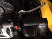
Hi All.. Havent posted very much - BUT I an trying to tailer my 2008 RS to a bit better ergonomics. The first major problem was lifting my foot to press the brake lever- Having to lift my foot up was not cool. I found my reaction time was way too slow. So I decided to add a HAND BRAKE (my Spyder is a SM5). Looking at ISCI and the like and the price blew my socks off- about $1800 by the time it would reach me in Canada. So I decided to engineer and machine my own solution sorta based on the same Idea.
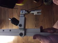
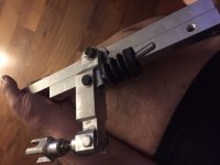
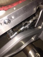
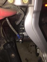
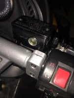
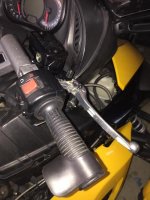
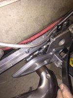
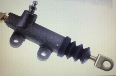
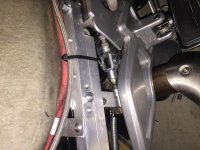
The mechanism is machined out of 6061-T6 aluminum with a stabilizing strut that extends from the rail to a frame bolt where the rear peg frame bolts on. The Master cylinder is from a 2014 Suzuki Vstrom DL650 (A bike I just sold, mine was a 2009) (was from a Bike parts yard), This brake is adjustable and has good volume as the Vstrom has dual front discs. I did have to make a custom clamp to fit the space on the RS and space it out a bit further) The Slave cylinder is a clutch slave cylinder off a Hyundai Tiburon (Amazon $23). Brake line is a nice stainless steel braided line 2 meters long (Amazon $22).
Brake actuation is positive and crisp- foot brake function is maintained and the whole system really is comfortable.
Total cost with all hardware, aluminum and brake components about $160 canadian (I did the machining and Autocad design myself).
Some pics for reference.. I did a cheesy Youtube video on the install https://www.youtube.com/watch?v=UGlQ8BlTF4g
Cheers
Dave
Attachments
-
 IMG_6961.JPG87.8 KB · Views: 93
 -
 IMG_6933.JPG77 KB · Views: 93
 -
 IMG_6931.JPG79.5 KB · Views: 109
 -
 5.jpg33.7 KB · Views: 108
 -
 7.jpg28.8 KB · Views: 98
 -
 spacer on brake handle.jpg30 KB · Views: 93
 -
 Vstrom brake.jpg38.1 KB · Views: 89
 -
 mech 2.jpg39.7 KB · Views: 91
 -
 clutch.jpg61.6 KB · Views: 82
 -
 A0701F60-5132-48B6-A664-5D5BA4D89202.jpg66.9 KB · Views: 41