• There were many reasons for the change of the site software, the biggest was security. The age of the old software also meant no server updates for certain programs. There are many benefits to the new software, one of the biggest is the mobile functionality. Ill fix up some stuff in the coming days, we'll also try to get some of the old addons back or the data imported back into the site like the garage. To create a thread or to reply with a post is basically the same as it was in the prior software. The default style of the site is light colored, but i temporarily added a darker colored style, to change you can find a link at the bottom of the site.

After Part number for 2010 RT-622 Turn Signal Socket? (also used on Spyders)

BertRemington

New member
Amber Turn Signal and Reverse Light for RT-622

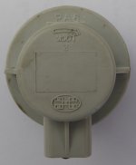
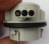
The 2010 RT-622 trailers came with Amber turn signals mounted in a removable socket. I believe the socket had two wires but included an option for three wires so the same part could be used for combination turn/brake signal by adding the third wire.

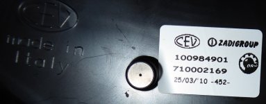
The socket is identified by a PA6 part number and a logo.

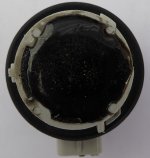
Starting in 2011 the RT-622 trailers moved the turn signal function to the combination tail/brake assembly. The turn signal mount was filled with a blanking socket that consisted of the wires cut off and a silver cover over a potted interior.
PA6 Front.JPG
PA6 Rear.JPG
PA6 Pins.JPG
Based on bulb matching, I believe this same socket is used for the RT Amber turn signals.

The rear light assembly is made for BRP by Zadi Group in Italy.
RT-622 Light Assembly.JPG
I haven't been successful after a half-hour search for a source for the socket. I've never done an image search and being lazy I thought maybe someone here would be faster.

My objective is to restore the Amber turn signals (using the awesome Auxito LEDs) to the post-2010 RT-622s and add reverse light LEDs. So we're looking at the following wire functions: Ground; Tail Lights (Red); Brake Lights (Red); Left Turn (Amber); Right Turn (Amber); and Reverse (White). I believe many people are using the 4-wire connector so the changes can easily be accommodated with a second 4-wire connector. An appropriate adapter/convertor/protector will be needed on the Spyder side. Note that the reverse power wire is available in same location (left-hand saddle bag area).
 
Last edited:
Amber Turn Signal and Reverse Light for RT-622

The good news is the bulb socket is also used in the RT rear light assemblies. And it seems to be used in other BRP vehicle lighting assemblies.

The bad news is the bulb socket is always integrated into the light assembly's wiring harness and therefore isn't available separately with its own pigtail. And it has an uncommon 3-key design rather than the more common 4-key design.

If the socket interior wasn't potted I could have made it work even though the two wires had been trimmed flush.

I found some wired 3-key design repair kits (eg, Dorman) that might fit. However they take 3156/3157 bulbs, not a particularly high hurdle.

Next step is to buy some and see if I can whittle them fit.
 
Amber Turn Signal and Reverse Light for RT-622

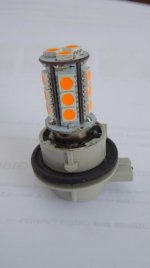
The hard part is done! Here's an Amber 7507 LED in the Turn Signal socket.
PA6 with Amber LED.jpg
So I was searching through my socket choices at Amazon and eBay. Same offerings at both sites, none of them particularly good. I went out to the trailer to take another look at a socket and the potting compound felt a bit soft (it was a hot day). And after an hour the Amber LED (https://www.superbrightleds.com/mor...8-smd-led-tower-bau15s-retrofit-car/527/12717) fit into the socket. I boiled water in the microwave to keep softening the potting compound and picked at it with a box knife and small screwdrivers -- not the right tools but that's all I had in my San Diego workshop. Some brake cleaner helped clean out loose material. Since I was already logged into Amazon I bought some picks for the other three sockets; arriving Wednesday.

Next step is to extend the wires and build the 6-wire trailer harness. First I have to ring out my current harness. I have the round 9-pin connector but it isn't clear how many pins are populated with trailer-to-Spyder wires. Also the Spyder's protector/convertor will need to be replaced to enable the separate turn signals.

Things are moving forward!
 
WooHoo Spyder-to-Trailer cable is easy!

I removed the 4-wire Spyder-to-Trailer cable by disassembling the 4-pin Deutsch connectors underneath the trailer and pulling it out of the drawbar (if someone wants the cable and connectors let me know -- it has the ground wire fix). While the cable has four wires the round connector has nine pins so I tried to access the back of the connector to add more wires. I wasn't successful but found this 9-wire cable as a replacement https://www.ebay.com/itm/252959292618?hash=item3ae58c7cca:g:qh8AAOSwEHpZKELt (Deutsch HD16-9-1939S-P080 (AHD16-9-1939S80) 9 PIN green type 2 cable, 72"). Easy peasy.

I then examined the 9-pin connector in the Spyder. Bummer -- it was molded into the adapter module. So to determine what my next step would be I examined the 13 wires and two 10-pin connectors comprising the adapter harness:

2@Blk -- Ground
2@Org -- Position (Tail and Marker)
2@Brn/Yel -- Right Turn
2@Gry/Pnk -- Left Turn
2@Wht -- Brake
2@Pnk/Tan -- Backup
1@Blu/Red -- RFB F4 10amp (Trailer) to RFB J2 40amp (Accessories) [Always-On]

The Trailer power is used for the trailer lights so no load is placed on the Spyder lighting circuits.

Earlier I read Dynamo's FS post for his trailer (still available https://www.spyderlovers.com/forums/showthread.php?145170-RT622-Trailer-Silver) where he replaced the incandescent turn signal bulbs with LEDs. Hmm Canada must use a different Spyder-to-Trailer cable and intra-trailer wiring harness. Dynamo was very helpful answering my questions -- thank you.

Dynamo said he had four turn signal bulbs. Checking the 2010 trailer parts catalog showed the bulbs were 7507s, same as the RT turn signal bulb. Which matched my four PA6 bulb holders -- all for 7507s. None were the 1156 backup bulb.

I was having dark thoughts about ordering a 9-pin bulkhead connector and chopping up the adapter cable but then it was Beer Time for me and my cat.

I started doodling possible module circuits and wondering why BRP had different modules for different trailers. And then I realized BRP had just one module and multiple country-specific Spyder-to-Trailer cables and intra-trailer wiring harnesses (and rear light assemblies)!

My new 9-wire cable arrived today so plugged it into the adapter and here are the results:
[table="width: 300"]
[tr]
[td]Pin[/td]
[td]Color[/td]
[td]Light[/td]
[/tr]
[tr]
[td]A[/td]
[td]Org[/td]
[td]Ground[/td]
[/tr]
[tr]
[td]B[/td]
[td]Yel[/td]
[td]Position (Tail & Marker)[/td]
[/tr]
[tr]
[td]C[/td]
[td]Red[/td]
[td]Brake (Right)[/td]
[/tr]
[tr]
[td]D[/td]
[td]SBlk[/td]
[td]Brake (Left)[/td]
[/tr]
[tr]
[td]E[/td]
[td]Blu[/td]
[td]Backup[/td]
[/tr]
[tr]
[td]F[/td]
[td]Grn[/td]
[td]Right Turn[/td]
[/tr]
[tr]
[td]G[/td]
[td]Brn[/td]
[td]Left Turn[/td]
[/tr]
[tr]
[td]H[/td]
[td]Vio[/td]
[td]Right Turn & Brake[/td]
[/tr]
[tr]
[td]J[/td]
[td]DBlk[/td]
[td]Left Turn & Brake[/td]
[/tr]
[/table]
BRP US Pin Assignments
[table="width: 300"]
[tr]
[td]Pin[/td]
[td]Color[/td]
[td]Light[/td]
[/tr]
[tr]
[td]A[/td]
[td]Blk[/td]
[td]Ground[/td]
[/tr]
[tr]
[td]B[/td]
[td]Brn[/td]
[td]Position (Tail & Marker)[/td]
[/tr]
[tr]
[td]H[/td]
[td]Grn[/td]
[td]Right Turn & Brake[/td]
[/tr]
[tr]
[td]J[/td]
[td]Yel[/td]
[td]Left Turn & Brake[/td]
[/tr]
[/table]
BRP CA Pin Assignments
[table="width: 300"]
[tr]
[td]Pin[/td]
[td]Color[/td]
[td]Light[/td]
[/tr]
[tr]
[td]A[/td]
[td]Blk[/td]
[td]Ground[/td]
[/tr]
[tr]
[td]B[/td]
[td]Org?[/td]
[td]Position (Tail & Marker)[/td]
[/tr]
[tr]
[td]C[/td]
[td]Wht?[/td]
[td]Brake (Right)[/td]
[/tr]
[tr]
[td]D[/td]
[td]Wht?[/td]
[td]Brake (Left)[/td]
[/tr]
[tr]
[td]F[/td]
[td]Brn/Yel?[/td]
[td]Right Turn[/td]
[/tr]
[tr]
[td]G[/td]
[td]Gry/Pnk?[/td]
[td]Left Turn[/td]
[/tr]
[/table]
My Pin Assignments
[table="width: 300"]
[tr]
[td]Pin[/td]
[td]Color[/td]
[td]Light[/td]
[/tr]
[tr]
[td]A[/td]
[td]Org[/td]
[td]Ground[/td]
[/tr]
[tr]
[td]B[/td]
[td]Yel[/td]
[td]Position (Tail & Marker)[/td]
[/tr]
[tr]
[td]C[/td]
[td]Red[/td]
[td]Brake (Right)[/td]
[/tr]
[tr]
[td]D[/td]
[td]SBlk[/td]
[td]Brake (Left)[/td]
[/tr]
[tr]
[td]E[/td]
[td]Blu[/td]
[td]Backup[/td]
[/tr]
[tr]
[td]F[/td]
[td]Grn[/td]
[td]Right Turn[/td]
[/tr]
[tr]
[td]G[/td]
[td]Brn[/td]
[td]Left Turn[/td]
[/tr]
[/table]
So I don't have to make any changes to the Spyder-end wiring!

So my next step is adding wires to the intra-trailer harness. And my cat is telling me it's Beer Time.
 
Just learned Australians are ... different

Peter Aawen just informed me that RT-622 (and other trailers) in Australia must have turn signals separate from brake lights (eg, America's 4-pin standard) and must have backup lights. Thanks Peter.

So that completes the last piece of the puzzle for the 710001811/710002433 9-pin adapter module: why there are 13 wires Spyder input to the module and 9 pins trailer output from the module.

The Australian country-specific drawbar cable configuration is the same as the "My Pin Assignments" table above.

I've finished the drawbar and intra-trailer wiring. Now I need to stop procrastinating and finish the light assembly wiring.
 
Back
Top