• There were many reasons for the change of the site software, the biggest was security. The age of the old software also meant no server updates for certain programs. There are many benefits to the new software, one of the biggest is the mobile functionality. Ill fix up some stuff in the coming days, we'll also try to get some of the old addons back or the data imported back into the site like the garage. To create a thread or to reply with a post is basically the same as it was in the prior software. The default style of the site is light colored, but i temporarily added a darker colored style, to change you can find a link at the bottom of the site.

2021 RT GPS wiring issues

MONK

New member
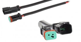
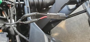
I installed my new zumo XT last weekend. I successfully removed (and reinstalled without any extra parts!) the right side tupperware and found the GPS plug. Either I'm doing something wrong or there's an issue with the bike. I bought a continuity test light (with a battery, never seen one of those before) and hooked the ground lead to a bolt head and (with the bike running) touched the other end to both wires (separately, of course). One caused the light to come on. The other caused the light to barely glow but it did come on. Had I not been inside my "garage", I wouldn't have seen it. Anyway, I hooked up the wiring with positive from the GPS to the wire that caused the test light to come on full strength. I didn't get power to the GPS (it continued to run off the battery). I even tried it the other way with the same result. I ended up connecting directly to the battery (it powers up so the problem isn't w/the GPS). I don't like this but will accept it for now until I figure out what I did wrong so I can wire it up the right way. I don't want to remove the tupperware again until I have a good grasp on how to fix this.

Anyone have any suggestions, please? Saturday's going to be a nice day to ride but next Sunday might not so I'd like to fix the wiring then, if possible.

HAGO!
 
If you connected the GPS to the Spyder's GPS plug, did you turn on the ignition switch to see if the GPS turned on? The GPS plug is connected to the ignition switch on my '14 and later model years but I don't know about MY 2020/21.
 
If you connected the GPS to the Spyder's GPS plug, did you turn on the ignition switch to see if the GPS turned on? The GPS plug is connected to the ignition switch on my '14 and later model years but I don't know about MY 2020/21.

I did, Jay. It wasn't getting power (except via the GPS internal battery). I tried it with both the key on (bike off) and with the bike running.
 
The test light you bought was looking for continuity. The wire that turned on the light bright was the ground(probably the solid colored one) the other wire with a strip on it is the hot wire. So you hook it ups backwards. Hopefully the GPS has reverse polarity protection build in. You should have a multi-meter for such work that indicates polarity. I just hooked up at dual USB/volt meter to that GPS 2 cable and used my multi-meter to find the correct polarity.

"This instrument is designed to test for continuity in a single wire or fuse. It can also be used to test switches, fuses, circuits, and cables on electrical control equipment, panelboard wiring, and more. Not for use on line voltage."
https://www.grainger.com/product/1E...ucid=N:N:PS:Paid:GGL:CSM-2295:4P7A1P:20501231
 
Check your Spyder fuses. You may have blown the one to the gps wire if you indeed hooked it up backwards.
 
Go to Harbor Freight and get the $6. multimeter (it's red). As Smoking said, continuity tester is a battery operated lightbulb that will light when the 2 leads (or probe) complete a circuit (short). The multimeter lets you measure voltage as well as open/shorts and resistance.
Use the meter to test the 2 wires in the GPS plug for proper polarity. The display will indicate a '-' (minus) sign if the polarity is reversed. Expect to see ~+12v when red lead is on the hot wire and black lead is on the ground wire and key is ON. If you popped the fuse, look for fuse #6 or 7 up front behind the frunk.
 
Yes, for some reason, the Spyder power harness has the GPS power connection reversed from the Garmin harness. DAMHIKT.
You can solve the problem the same way Scotty from Star Trek fixes all of the problems on the Enterprise. Reverse the polarity.
 
The test light you bought was looking for continuity. The wire that turned on the light bright was the ground(probably the solid colored one) the other wire with a strip on it is the hot wire. So you hook it ups backwards. Hopefully the GPS has reverse polarity protection build in. You should have a multi-meter for such work that indicates polarity. I just hooked up at dual USB/volt meter to that GPS 2 cable and used my multi-meter to find the correct polarity.

"This instrument is designed to test for continuity in a single wire or fuse. It can also be used to test switches, fuses, circuits, and cables on electrical control equipment, panelboard wiring, and more. Not for use on line voltage."
https://www.grainger.com/product/1E...ucid=N:N:PS:Paid:GGL:CSM-2295:4P7A1P:20501231

The wire that lit up the light brightly was the multicolored one. Are you saying that this device is what I need or an example of what I DON'T need? I've got a nice multimeter (that I've never used) (Southwire 21010N). No idea why I bought it several years ago and I'm not really sure how to use it. It's got a setting for V/Hz but when I touched each wire (with the red probe...touched the black probe to ground), I got some funky numbers. I tried to look up the directions but they just got me more confused.
 
So set your multi meter to AC/DC voltage, Black lean in common input jack and Red in positive V input jack. Then probe the two wires. When you get +12 V note which wire the red lead is on. Reversing the leads should show -12V. We already pretty much know that if you declared the lead the lite up your continuity probe bright that was the ground and the dim one was showing the difference between the trikes 12V and the battery voltage of the probe which was close.

So, when I get a POSITIVE reading, the wire the RED probe is on is the hot, correct?
 
Could be the case on mine but I'd hate to fry the GPS. I need to be sure which is which then I can check the fuse and wire it up correctly.

So set your multi meter to AC/DC voltage, Black lean in common input jack and Red in positive V input jack. Then probe the two wires. When you get +12 V note which wire the red lead is on. Reversing the leads should show -12V. We already pretty much know that if you declared the lead the lite up your continuity probe bright that was the ground and the dim one was showing the difference between the trikes 12V and the battery voltage of the probe which was close. Thus you reversed the polarity.

From the manual: Garmin®
strongly recommends having an experienced installer
with the proper knowledge of electrical systems install the
device. Incorrectly wiring the power cable can result in damage
to the vehicle or the battery and can cause bodily injury.
 

Attachments

  • PXL_20201130_211850631.jpg
    PXL_20201130_211850631.jpg
    93.2 KB · Views: 23
Also remember to have the key turned on as there is only power when it's on. Spyder doesn't have to be running.
 
MONK, did you get the power issue figured out?

I don't usually have much time during the week due to work. I'll work on it Saturday. It's supposed to rain so it's not like I was going to ride anyway. I hope everything's resolved by lunch on Saturday. :) I'll report back, one way or another.

HAGO!
 
Thank you all for the help. I rewired things today and am now using the correct BuRP GPS plug which works perfectly. I bought some Dutch connectors I bought from Amazon. (I know I mispelled that but you know what I'm talking about.) I want to be able to unwire it easily if needed in the future. I also had to replace the fuse. You guys were right that at some point I blew the fuse.

I used Posi Locks to connect the bike wiring to the Dutch connector and the connector to the Garmin wiring harness then overtaped everything....just in case. In hindsight, I should have soldered/shrinkwrapped the connections which I may do sometime in the future.
 

Attachments

  • Dutch connectors.jpg
    Dutch connectors.jpg
    23.9 KB · Views: 52
  • 20201205_131143.jpg
    20201205_131143.jpg
    42 KB · Views: 53
Back
Top