• There were many reasons for the change of the site software, the biggest was security. The age of the old software also meant no server updates for certain programs. There are many benefits to the new software, one of the biggest is the mobile functionality. Ill fix up some stuff in the coming days, we'll also try to get some of the old addons back or the data imported back into the site like the garage. To create a thread or to reply with a post is basically the same as it was in the prior software. The default style of the site is light colored, but i temporarily added a darker colored style, to change you can find a link at the bottom of the site.

Can anyone with a Big Blue Lift provide advice on my lifting issues?

It's been a while since I've bothered to use it/all the Big Blue's features, and I can't quite picture where that bit is atm (you got a better pic?? One showing all if the arms/components that match up to the Spyder maybe?? :unsure:

I'm not in a position/able to dig BB out atm, he's under too much stuff that's been used more recently! Kids, why can't they put things back where they came from!! And who was it who said "They'll get better once they've turned 20... then 30... then 40; only now they're all over 40, and they STILL aren't any better at that! 😣 But...

Doesn't that hinged bit flip up so that as you slit the jack underneath and then raise it, that bit inserts up into the gap on the other (or front?) side (end?) of the spar, helping hold the whole thing secure and stopping it slipping off BB?? :unsure:

Like I said, it's been a while, and my forgettory does sometimes work overtime on details like that (but my muscle memory is good, I can still run the forms with or without a sparring partner, and drive the Test Track at the Bend blindfolded without missing a corner or hitting a kerb, a bump, or a guard rail! 😁)

Oh, so that mess in the garage is somebody else's fault? Ha!

I'll take some more pics and post them. Tomorrow. After I clean out the mess my neighbor's distant relatives left behind after camping out for a week because he didn't want them crashing at his place when they dropped in unexpectedly on their way through on their annual pilgrimage to ...never mind
 
Okay, @Peter Aawen I'm inclined to agree with you that the piece in question is designed to be flipped up somehow after getting BB under the Spyder so that it, together with the rear bracket under the bike's rear shock, contribute to overall stability. The instructions that come with the lift don't mention it at all, that I can find anyway, hence the question.

(Update, this is incorrect. It's fixed, not hinged)

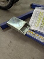
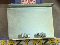
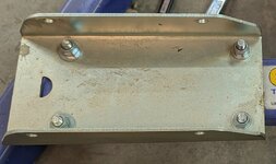
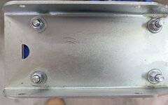
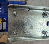
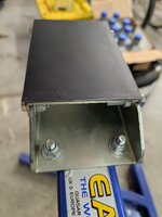
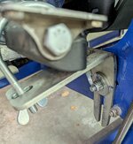
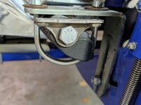
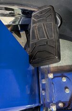
There are four bolt holes in the plate and in the lifting arm, so it may be that it's designed to be bolted flush on top of the arm, just so the u-channel of the arm isn't biting into the bike frame. (True)

Or, as you say, it's designed to be bolted just at one end so it can flip up after the lift is under the frame. The problem with the latter explanation is that with the bolts in place it won't flip up up very far because of a tang on the trailing edge of the plate.

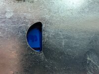
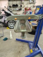
Anyway here's the pics.
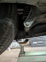
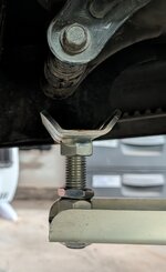
PXL_20261017_180231204.jpg - PXL_20261022_034650279.jpg - PXL_20261022_034639104.jpg - PXL_20261022_034630012.jpg
 
Last edited:
Orright, I've had a bit of a dig thru the layers and managed to get a thorough cursory glance at the BB buried in my shed... 🤪

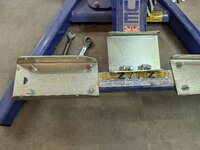
For whatever it's worth, I reckon there's meant to be FOUR (4) bolts securing that plate you pictured in post #19, bolts that match up to the holes in the sides of the channel underneath. That plate section is meant to be bolted down (as in your first pic) by those 4 bolts so as to form a flat surface for the front of the Spyder's main spar to sit on.

I appear to have an extra piece of metal/channel bolted onto the BB in my shed, using the front two bolts (the two bolts that your pic DOESN'T have/show) so that, once the extra bit is flipped up vertically, it has a flat section (which is almost as wide as the channel below) that projects upwards so that it can positively locate the front of the Spyder by slotting neatly into a hole/slot cut into the rear edge of the alloy skid plate that I have bolted underneath my Spyder (an alloy skid plate which juuust overlaps the front of the main spar) where many of you North American Spyder owners might have a Bumpskid or similar mounted, at least if you no longer have the OEM piece of flimsy plastic skid plate still mounted there, anyway?!

This/however many years it is down track, I no longer know for sure, but I have a fairly strong feeling that this extra bit of channel I have there may have been a 'Peter Aawen add-on' designed to positively locate the Spyder on the front end of the lifting arm by keying the add-on flip up bit into that slot cut in the middle rear of my alloy skid plate; cos without it, that flat front section you are questioning is just a flat pad of shiny metal that has another flat pad of slippery Spyder main spar sitting on it, basically only located by the weight of the Spyder and that pain in the **** flimsy 'U-clamp' thingy around the foot peg... And when I was using BB for other's Spyders, I had a thick rubber pad that sat on the top of that flat piece you're asking about (& over my 'add-on flip up bit too) in an effort to avoid leaving flat shiny metal supporting the weight of the front end of the Spyder under the front of its flat (sorta shiny) main spar... Make sense? :unsure:

Over to you... ;)
 
As stated elsewhere the plate must be bolted on with 4 bolts and should have a hard rubber plate bonded on top as an anti slip feature. There are two heights of metal plate depending on model year. I think 2020 and on are higher ie from the top of plate to the bolt holes. Also the semi circular cut out in the bottom plate is used as a positioning reference for distance from the end of the blue lift arm. I think I can look it up if you want.
I have used my Big Blue on several different bikes over the years and found it indispensable.
Alan.
 
@Peter Aawen makes complete sense. So, the bit on the left gets flipped upside down and bolted to the bit on the right with four bolts, to provide a flat surface for the front of the Spyder frame to rest on?

@Flier Tuck if you could provide a reference or pics, that would be a great help. You're saying the two parts get bolted together as described above, then the whole thing gets slid back and forth along the BB main lifting arm until the semi-circular cutout aligns with a reference point on the main lifting arm, depending on the model of spyder being lifted?

20261022_081729.jpg - PXL_20261022_034650279.jpg
 
Last edited:
@Peter Aawen makes complete sense. So, the bit on the left gets flipped upside down and bolted to the bit on the right with four bolts, to provide a flat surface for the front of the Spyder frame to rest on?

@Flier Tuck if you could provide a reference or pics, that would be a great help. You're saying the two parts get bolted together as described above, then the whole thing gets slid back and forth along the BB arm until the semi-circular cutout aligns with a reference point, depending on the model of Spyder being lifted?

View attachment 257473View attachment 257474

Yes to the first bit you've got up there, but I think it's a No to the second! :unsure:

IIIRC, and I think @Flier Tuck's post supports this, the semi-circular cut-outs are reference points that are used to position each of the bolted on Spyder brackets that those cut-outs are in onto the respective ends of the Big Blue lifting arm that those pieces of metal/lifting brackets are bolted on to; before you bolt the flat lifting plate/cover thingy onto the channel the cut-out is in, you can look thru the semi-circular cut-out to see and align the straight edge of the cut-out in the bracket with the end of the BB lifting arm that's exposed thru the cut - but the cut-outs actually have nothing to do with positioning the Spyder itself that you might be lifting, regardless of the model! So if that's what you're trying to say above, then you are correct and that one's a Yes too, otherwise... ;)

Make sense?? :sneaky:
 
I'm now re-reading, with a bit more understanding, the instructions that come with the adapter for the RT, and it's starting to make sense. It says:

Assemble the mounts to the lift with the Front Mount (left side) aligned so that the straight edge of the "D" shaped "window" cut into the mount is level with the end of the main lifting arm, like this:​
​
PXL_20261022_161859582.jpg​
​
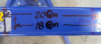
Now take the Rear Mount (right side) and position the straight edge of the "D" shaped window approximately 20mm inward from the end of the main lifting arm, like this:​
​
PXL_20261022_162835068.jpg - PXL_20261022_162941842.jpg - PXL_20261022_162946911.jpg​

Ignore the 20cm markings - that's a mistake. The 18cm mark is where the left edge of the rear mount lines up.
 
Last edited:
Next, the instructions say to:

Assemble the adjustable rear pillar, but do not tighten the 30mm nuts until the lift has been offered to the bike and the required height position is determined...​
​
PXL_20261022_165309804.jpg​

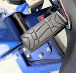
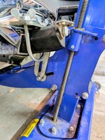
As mentioned above, and as shown in a Pic in the instructions, the Front Mount is supposed to have a rubber pad, but my (used) BB lift had none, so I fashioned one from some scrap vinyl baseboard. My Front Mount was also missing two of the four bolts needed, so I used 5/16 bolts instead.

PXL_20261022_173203842.jpg

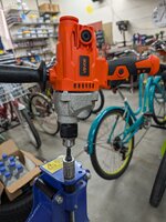
The last gratuitous pic is of my new hi-torque/low speed mixing drill motor, which makes quick work of raising and lowering the lifting arms

PXL_20261022_165256780.jpg
 
At this point the instructions get a little vague. They say to remove the right floorboard (okay) then slide the lift under the bike from the right side, without mentioning there's not enough clearance.

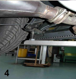
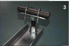
Align the BB main lift arm with the bike's spine and position the rear mount under the bike's "rear suspension arm". I think, from the pictures given, that they mean the rear shock bottom mounting bracket. Once done, raise the rear mount pillar, then fit the two u-bolts around them. This requires more space than would be available without having raised the bike considerably, I think.​
​
Big Blue Eazy-Rizer Spyder-RT-inc-2020 photos 4.png - Big Blue Eazy-Rizer Spyder-RT-inc-2020 photos 3.png​
 
Last edited:
At this point the instructions get a little vague. They say to remove the right floorboard (okay) then slide the lift under the bike from the right side, without mentioning there's not enough clearance.

Align the BB main lift arm with the bike's spine and position the rear mount under the bike's "rear suspension arm". I think that, from the pictures they mean the rear shock bottom mounting bracket. Once done, raise the rear mount pillar, then fit the two u-bolts around them. This requires more space than would be available without having raised the bike considerably, I think.​
​

Are you sure that your Spyder hasn't settled/lost a bit of ground clearance over the years (and miles) that juuuust might be making this bit more of an issue than it should be/needs to be?? :unsure:

Just Askin' ;)
 
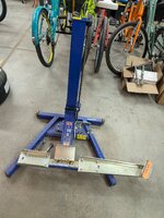
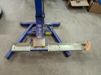
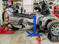
I just purchased a 24 S2S. I also purchased a new Big Blue lift, put it together followed the directions, and went to lift the bike up. As you can see in the pic, the left side won't lift. The right tire is up around 2 5/8 of an inch and the rear is up around 2 7/8 of an inch. I am centered in the front and in the back the bike is a little wobbly, nothing crazy. The front mount is right at the edge as per the instructions and the rear mount is at 13/16 of an inch as per the instructions or 20mm. If anyone with this lift has any advice, I would be grateful.

View attachment 211662
For the first few attempts to raise and lower the lift, I opted to do so manually. This gave me better understanding of how the machine would list and/or roll and allowed for me to stop quickly and drop the lift and perform any slight adjustments below. I always raise the machine manually until I know that the full weight of the machine is on the front and rear mounts before I install the side bracket mount to the floorboard socket. Be sure to use the floorboard mount but be sure you're not tightening it to the floorboard sockets too soon, or you'll risk bending the bracket itself by putting too much weight of the machine on that bracket. The entire weight of the bike should be on the front and rear lift mounts; the side mount is intended to prevent the machine from tilting away from the lift. Once I have the side mount bracket secured (I also use a 1/2 spacer washer here) I use my power drill for the rest of the ride. For the rear cradle, check to make sure that the cradle pillar is not unscrewed so far that it causes the pillar to tilt. The entire process is a bit nerve-wracking until you get the hang of what movement to expect before the entire unit settles in and becomes stabilized. But I'm pretty sure you've trialed and errored all of this by now.
 
For the first few attempts to raise and lower the lift, I opted to do so manually. This gave me better understanding of how the machine would list and/or roll and allowed for me to stop quickly and drop the lift and perform any slight adjustments below. I always raise the machine manually until I know that the full weight of the machine is on the front and rear mounts before I install the side bracket mount to the floorboard socket.
That is what they say to do, you're right. I've been doing that wrong.
Be sure to use the floorboard mount but be sure you're not tightening it to the floorboard sockets too soon, or you'll risk bending the bracket itself by putting too much weight of the machine on that bracket.
That is happening. Also, it tends to shift the BB back away from the bike, misaligning it with the spine when that happens. I'll go back and start from scratch. Thanks.
The entire weight of the bike should be on the front and rear lift mounts; the side mount is intended to prevent the machine from tilting away from the lift.
It does, that's true. Back to the drawing board...
Once I have the side mount bracket secured (I also use a 1/2 spacer washer here) I use my power drill for the rest of the ride. For the rear cradle, check to make sure that the cradle pillar is not unscrewed so far that it causes the pillar to tilt. The entire process is a bit nerve-wracking until you get the hang of what movement to expect before the entire unit settles in and becomes stabilized. But I'm pretty sure you've trialed and errored all of this by now.
 
That part is maddening. I usually lay on the ground while reaching the top of the lift and crank the socket while I watch where the front and rear mounts will land. My neighbor saw me craning in that position and was compelled to come over to make sure I was okay. It's nice to have such great neighbors!
 
Okay, well, I still have it up on the BB lift, but lowered it enough to take the stress off the floorboard bracket so I could try to get the BB pushed far enough under the bike to center the front mount on the spine.

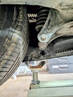
But then what I am encountering is the brake pedal is hard against the column, preventing the BB from being able to be moved toward the front of the bike, making alignment of the rear mount and shock mount iffy.
PXL_20261022_215926165.jpg - PXL_20261022_220429913.jpg - PXL_20261022_220024120.jpg
With the BB floorboard bracket underneath the floorboard mount and the U-bolts on top, the BB bracket can't be lowered enough so that it doesn't take the weight of the bike before the lift arms do.
PXL_20261022_211749934.jpg
With the BB bracket turned upside down it doesn't have enough length to engage with the bolt. This picture shows it with it taking the bike's weight.
PXL_20261022_220043599~2.jpg
I'm taking a break for now and maybe in the meantime you folks will notice something obvious I'm doing wrong.
 
Last edited:
Can you pull the lift away from the bike and take a closeup photo of the floorboard sockets on the bike frame? Something doesn’t look right from the images you’ve shared.
This is the pre-2020 RT. It doesn't use the floorboard mounting bolt holes like the 2020 and later. Is that what you mean?
 
Back
Top