• There were many reasons for the change of the site software, the biggest was security. The age of the old software also meant no server updates for certain programs. There are many benefits to the new software, one of the biggest is the mobile functionality. Ill fix up some stuff in the coming days, we'll also try to get some of the old addons back or the data imported back into the site like the garage. To create a thread or to reply with a post is basically the same as it was in the prior software. The default style of the site is light colored, but i temporarily added a darker colored style, to change you can find a link at the bottom of the site.

Need to Replace Parking Brake Cable, re-align actuator wheel, & fix the micro-switch!

Pappy3

New member
Need to Replace Parking Brake Cable, re-align actuator wheel, & fix the micro-switch!

2014 RT
So I messed up while replacing rear pads.
Didn't get the caliper bracket hooked over the onside "bump" of the swingarm.
Short test ride and the caliper spun a bit and broke the cable free from the rear attachment.

Found a replacement cable and proceeded to install.
Oops, looks like the actuator wheel also spun.
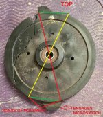
The hole for cable attachment moves between 7 and 8 o'clock.
Searching the web, it appears the hole should be at 11 and move to 12oclock.
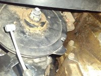
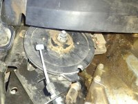
Put a wrench on the actuator nut but both the stub and nut turn.
Can't find anything to grab behind the pulley.
And yea, micro switch looks bent as well.
 

Attachments

  • IMG_20230529_100124226.jpg
    IMG_20230529_100124226.jpg
    95.1 KB · Views: 53
  • IMG_20230529_100102389.jpg
    IMG_20230529_100102389.jpg
    93.2 KB · Views: 48
Last edited by a moderator:
I did the same thing to our 2014 last year and broke the cable and pulley. I don't recall exactly how I held the new pulley in place while tightening the nut but, I'm pretty sure the tab next to the cable connection should be oriented to the top and moves between 11 and 1 o'clock while the tab 180° away is the one that actuates the microswitch. The microswitch paddle can be straightened and still function properly so long as the little wheel on the end of it was not destroyed. Sorry I can't be of more help on the pulley problem. Seems like there were flat spots behind it where a 15mm open end wrench fits to hold it while tightening the nut.
 
Thanks for the feedback. After a bit more research i agree with your pulley positioning.
Have removed pulley (15mm wrench to hold the bolt head) and motor.
Can't figure out (yet) how to remove the micro switch. Did straighten it out fairly well.
Will dig some more and do some experimenting.
Thx again!
 
I never had to remove the switch. Just used a couple different needle nose pliers, one straight and one bent nose and a pair of duck-bill pliers.
 
Last edited by a moderator:
From that picture, I am thinking that unless you have had that pulley off and got it out of rotation, you'll have to take and push the reverse button until the pulley's in the most counterclockwise direction and it should be up against the microswitch on that side of the wheel, the switch is the stop point. Then you will have to take the cable off the caliper end by backing off the adjustment nuts and taking the cable off the pulley on that end, then install the cable on the top where it belongs, wrapping it onto the pulley the right way, then put it back on the caliper end, and adjust the tension on the cable to spec. The lobes on the wheel are the stopping points that are supposed to hit the switch and make the motor stop. Your wheel looks like it's out of sync somehow. I've seen where the cable gets pinched and pops off the wheel on the top, and the wheel should have stopped on that lobe. :dontknow: If something has happened to that switch and the wheel has gone too far, then you may have to take it to the shop because it will have to be replaced and then adjusted with Buds! At least that's what I am reading...
 
Last edited by a moderator:
I got by without a shop or BUDS.

I reasoned that the spring at the caliper end held the brake in the disengaged position. I then thought it only made sense the microswitch told the brake motor when to stop releasing tension on the cable. From those thoughts I decided that positioning my new pulley so the bottom tab just engaged the switch so it clicked but no more than that. After that I held the pulley in place with a couple of needle nose vice grips until I could get the new cable in place starting at the pulley end and routing it just as the old one had come out then hooking up the back end using a small pipe wrench to rotate the lever into the engaged position. This made it doable though challenging as I was working alone. I didn't have any specifications to go by so set the tension on the cable by measuring the amount of threads showing in the adjustments. Turned it on and cycled the brake on an off a few times and it worked so I called it all good and put all the panels back in place. It has worked fine since then.

In the picture, I have indicated range of motion and proper top & bottom orientation. hope this helps.
 

Attachments

  • rear brake pulley2.jpg
    rear brake pulley2.jpg
    90.5 KB · Views: 32
Last edited by a moderator:
Back
Top