Poppie65
Active member
Prior to installing the ST2 equipment, I had installed the Show Chrome Form Fusion Trunk Light kit with the Plug & Play wiring harness. All of the wiring work that was done for the ST2 was made to that harness. I did not have to cut any BRP wiring. I don't know if this harness can be purchased separately, but if it can be, I highly recommend doing so. This write up covers the installation of the ST2 brake module as well as the ST2 brake strobing module.


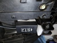
Placement of the module is limited the flat surface under the passenger seat where it is not contacted by the underside of the seat.

I initially applied self-adhesive Velcro strips in multiple layers in order to both hold the module in place as well as provide some cushion.

Since I used the plug & play harness from Show Chrome, the wire colors did not match the BRP wire color chart, but it was very easy to locate and follow the corresponding wires for the installation. As per recommendation from Tiny2 and Bert Remington, a diode was spliced into the signal wire to eliminate the possibility of disruption of the cruise control.


It's important to leave room in the signal wire to splice in the stroke module if it is being used


After riding over a couple of days I found that the module needed to be moved and the position "tuned" to eliminate some of the false signals that it was sending to the lights. I used some strips of foam insulation that is used in shipping to change the degree of slope and buffer any lateral impacts that the module may have experienced. It's operating quite well now, but may still need more tweaking. The slope can be set too far forward, this was the reason that I added padding under the leading edge of the module.


Very special thanks to Bert Remington for exceptional tutorial help and materials. You ROCK!
Placement of the module is limited the flat surface under the passenger seat where it is not contacted by the underside of the seat.
I initially applied self-adhesive Velcro strips in multiple layers in order to both hold the module in place as well as provide some cushion.
Since I used the plug & play harness from Show Chrome, the wire colors did not match the BRP wire color chart, but it was very easy to locate and follow the corresponding wires for the installation. As per recommendation from Tiny2 and Bert Remington, a diode was spliced into the signal wire to eliminate the possibility of disruption of the cruise control.
It's important to leave room in the signal wire to splice in the stroke module if it is being used
After riding over a couple of days I found that the module needed to be moved and the position "tuned" to eliminate some of the false signals that it was sending to the lights. I used some strips of foam insulation that is used in shipping to change the degree of slope and buffer any lateral impacts that the module may have experienced. It's operating quite well now, but may still need more tweaking. The slope can be set too far forward, this was the reason that I added padding under the leading edge of the module.
Very special thanks to Bert Remington for exceptional tutorial help and materials. You ROCK!
Attachments
Last edited:
