IdahoMtnSpyder
Well-known member
Here's my info on wiring a headlight modulator into the Spyder headlight circuit. I would have done this sooner but other matters took priority.
Unfortunately I forgot to take photos of the project as I was doing it. I also forgot to take them when I had the bike half apart to install the Tri-Axis handlebar. Sorry.
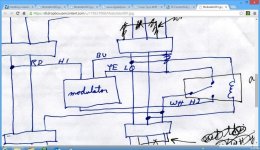
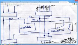
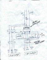
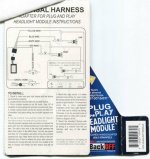
Below is the wiring diagram I sketched up to do the job. I did it this way to avoid directly modifying any of the OEM harness. That's just my preference. You can cut wires and splice the modulator and relay directly into the harness if you want. There's space behind and between the headlights to mount the modulator and relay but you have to be careful where you put the connectors because the space is kind of tight.
The connectors are 5 position AMP/TE Connectivity Superseal series 1.5 connectors. I bought them, as parts and pieces, from Newark Electronics. You can probably find them on eBay assembled with pigtails. The relay is a standard single pole double throw automotive relay from NAPA.
The reason for the relay is because the US/Canada Spyder headlight uses the low beam circuit for the bulb filament and the high beam is used to lift the shutter. The relay connects either the high or low beam modulator output to the headlight low beam wire as you switch between high and low. An alternative to using a relay is to connect the modulator outputs to the low beam wire with diodes. That way each output feeds the low beam wire without back feeding into the modulator. The downside is you always have about a 1 volt drop across a diode and I wasn't sure how that would affect the brightness of the headlight. You have to keep the modulator outputs isolated from each other in order to have the modulator switch on and off by flipping the high/low beam switch.
You will see on the diagram a jumper on the headlight side of the 5 pin connector. That jumper keeps the low beam relay activated all the time thus keeping power on the low beam wire all the time. If you make an adapter harness like I did you don't need to be concerned about it because you will break the circuit to and from the jumper. If you cut and splice the modulator into the harness then you need to cut the jumper. You can see the X on the diagram.
This system does cause some hesitation in the headlight when switching from high to low and vice versa. I think it's caused by the added relay being in series with the stock headlight power relays. Using diodes may well cure that problem.
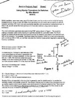
The modulator has an option to connect to the horn circuit. When you blow the horn the modulation switches between fast and slow rates to help attract attention. Two short horn blasts changes the modulator mode from slow to fast or vice versa. But the modulator lead needs a +12 volt signal to work and the Spyder horn button completes the horn circuit on the ground side. I solved that problem with a small transistor circuit which is discussed in the second page.
Hi res version: https://dl.dropboxusercontent.com/u/178527008/Modulator001.jpg
Hi res version: https://dl.dropboxusercontent.com/u/178527008/Modulator002.jpg
Hi res version: https://dl.dropboxusercontent.com/u/178527008/Modulator003.jpg
Unfortunately I forgot to take photos of the project as I was doing it. I also forgot to take them when I had the bike half apart to install the Tri-Axis handlebar. Sorry.
Below is the wiring diagram I sketched up to do the job. I did it this way to avoid directly modifying any of the OEM harness. That's just my preference. You can cut wires and splice the modulator and relay directly into the harness if you want. There's space behind and between the headlights to mount the modulator and relay but you have to be careful where you put the connectors because the space is kind of tight.
The connectors are 5 position AMP/TE Connectivity Superseal series 1.5 connectors. I bought them, as parts and pieces, from Newark Electronics. You can probably find them on eBay assembled with pigtails. The relay is a standard single pole double throw automotive relay from NAPA.
The reason for the relay is because the US/Canada Spyder headlight uses the low beam circuit for the bulb filament and the high beam is used to lift the shutter. The relay connects either the high or low beam modulator output to the headlight low beam wire as you switch between high and low. An alternative to using a relay is to connect the modulator outputs to the low beam wire with diodes. That way each output feeds the low beam wire without back feeding into the modulator. The downside is you always have about a 1 volt drop across a diode and I wasn't sure how that would affect the brightness of the headlight. You have to keep the modulator outputs isolated from each other in order to have the modulator switch on and off by flipping the high/low beam switch.
You will see on the diagram a jumper on the headlight side of the 5 pin connector. That jumper keeps the low beam relay activated all the time thus keeping power on the low beam wire all the time. If you make an adapter harness like I did you don't need to be concerned about it because you will break the circuit to and from the jumper. If you cut and splice the modulator into the harness then you need to cut the jumper. You can see the X on the diagram.
This system does cause some hesitation in the headlight when switching from high to low and vice versa. I think it's caused by the added relay being in series with the stock headlight power relays. Using diodes may well cure that problem.
The modulator has an option to connect to the horn circuit. When you blow the horn the modulation switches between fast and slow rates to help attract attention. Two short horn blasts changes the modulator mode from slow to fast or vice versa. But the modulator lead needs a +12 volt signal to work and the Spyder horn button completes the horn circuit on the ground side. I solved that problem with a small transistor circuit which is discussed in the second page.
Hi res version: https://dl.dropboxusercontent.com/u/178527008/Modulator001.jpg

Hi res version: https://dl.dropboxusercontent.com/u/178527008/Modulator002.jpg

Hi res version: https://dl.dropboxusercontent.com/u/178527008/Modulator003.jpg


