So a buddy of mine with a spyder bought a GPS like mine and had beer, so I made him a mount for him like I made for mine. This time I figured if I was making one, it would be just as easy to make three.
So first I started with a CAD rendering.
 Untitled by Uncle Grr!, on Flickr
Then I transferred that CAD to metal. I tack welded three pieces of steel together so I could cut three out simultaneously.
 Untitled by Uncle Grr!, on Flickr
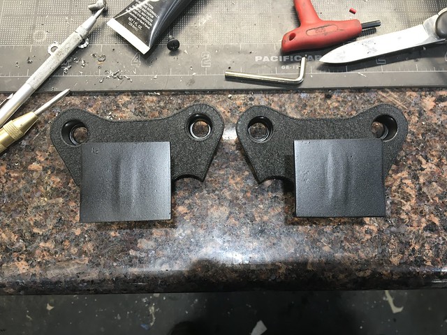
So after plasma/bandsaw cutting them out, cleaning them up, filing, adjusting, milling, flipping, sandblasting, etc. this is what I was left with.
 Untitled by Uncle Grr!, on Flickr
Next I made the actual post mounts. I have zero pictures for some reason but the short version is that I started with some .750 bar that I drilled through to some size that cleared the bolts. Then I used a .5" end mill to hog it out 7/16" deep, and ran a boring bar down .520" deep at whatever size I determined cleared the bolt head. Sorry for the weird mix of measurements but this is how it went. Then I knocked a step in the top however deep it needed to be to clear the hole I drilled in the top plate, at .050" long. It made a lot more sense when I was doing it. Some measurements were kept on the lathe dials, some were kept on the DRO. Anyway, I parted them off to .585" long to keep a .060" bottom thickness which is about the same thickness as the stock washer. Once all were made I set each one in the lathe, zeroed the DRO against the depth, moved the carriage to -.145 and cut in .015 with a tool set at some angle that seemed to work to chamfer the bottoms. Don't think too hard about this, the important thing is that all the parts I turned had the same chamfer at the bottom which fit the triple clamp nicely. I should mention that I made the top of these risers a press fit into the base plates, so I used the hydraulic press to press these in before I welded them from the bottom.
Edit: challenge the first is that my goodish three jaw check is awful and needs to be reground, but I haven’t gotten around to making the fixtures to do it. So I installed my four haw chuck, which is terrible ant excessively tight so it takes forever to indicate the part to center. That lasted one part before I srptarted looking for my ‘bad’ three jaw chuck, that only has a few thou of runout. Eventually found it behind a sander on one of my workbenches (wife helped clean after one of her projects) and did the rest with that chuck.
Then I grabbed some steel I had laying around that I had cut at some very specific angle for another project, and chopped it off in the big chop saw. Then I drilled through and installed a bolt to hold them together. I milled some angles into it that were visually pleasing.
 Untitled by Uncle Grr!, on Flickr
Then I marked center on the base plates and some perpendicular lines. I clamped the triple stack of risers to the base plate and welded the outside two. Once the outside two were welded, I pulled out the center one and inverted it. I also sandblasted the whole shebang in between each step.
 Untitled by Uncle Grr!, on Flickr
Then I squared up another chunk of steel and welded the center piece to the bottom. I then painted most of it and waited for my buddy, since I needed the GPS mount to get the final dimensions.
 Untitled by Uncle Grr!, on Flickr
So final dimensions turned out to be 2" wide by 1.75" tall, with four holes spaced .75" x .6" from center. Simple like pie. I drilled the mounts and used an M5x16 SHCS and nut to clamp the whole shebang together. After we stripped his bike and ran the wiring as I did in my other GPS post, with the caveat that BRP wired the GPS plug backwards relative to the mating plug I bought off amazon. He seems happy, and I have two spare GPS mounts. I'm currently deciding whether to just keep them on hand as spares or put them in the for sale forum. Any interest?
 Untitled by Uncle Grr!, on Flickr
Yes I know this is an awful step by step instruction. That's kind of how it went though. The correct depth for the boring bar was set as zero on the DRO, didn't matter what actual size it was. Depth for the step on top to press into the base plate was set at zero on the cross slide dial, didn't care what the measurement was. Etc. There was a fair amount of hand fitting, and this was an all day project for the three mounts. X zero was reset for each operation. Fun though.
 Untitled by Uncle Grr!, on Flickr
So first I started with a CAD rendering.
Untitled by Uncle Grr!, on FlickrThen I transferred that CAD to metal. I tack welded three pieces of steel together so I could cut three out simultaneously.
Untitled by Uncle Grr!, on FlickrSo after plasma/bandsaw cutting them out, cleaning them up, filing, adjusting, milling, flipping, sandblasting, etc. this is what I was left with.
Untitled by Uncle Grr!, on FlickrNext I made the actual post mounts. I have zero pictures for some reason but the short version is that I started with some .750 bar that I drilled through to some size that cleared the bolts. Then I used a .5" end mill to hog it out 7/16" deep, and ran a boring bar down .520" deep at whatever size I determined cleared the bolt head. Sorry for the weird mix of measurements but this is how it went. Then I knocked a step in the top however deep it needed to be to clear the hole I drilled in the top plate, at .050" long. It made a lot more sense when I was doing it. Some measurements were kept on the lathe dials, some were kept on the DRO. Anyway, I parted them off to .585" long to keep a .060" bottom thickness which is about the same thickness as the stock washer. Once all were made I set each one in the lathe, zeroed the DRO against the depth, moved the carriage to -.145 and cut in .015 with a tool set at some angle that seemed to work to chamfer the bottoms. Don't think too hard about this, the important thing is that all the parts I turned had the same chamfer at the bottom which fit the triple clamp nicely. I should mention that I made the top of these risers a press fit into the base plates, so I used the hydraulic press to press these in before I welded them from the bottom.
Edit: challenge the first is that my goodish three jaw check is awful and needs to be reground, but I haven’t gotten around to making the fixtures to do it. So I installed my four haw chuck, which is terrible ant excessively tight so it takes forever to indicate the part to center. That lasted one part before I srptarted looking for my ‘bad’ three jaw chuck, that only has a few thou of runout. Eventually found it behind a sander on one of my workbenches (wife helped clean after one of her projects) and did the rest with that chuck.
Then I grabbed some steel I had laying around that I had cut at some very specific angle for another project, and chopped it off in the big chop saw. Then I drilled through and installed a bolt to hold them together. I milled some angles into it that were visually pleasing.
Untitled by Uncle Grr!, on FlickrThen I marked center on the base plates and some perpendicular lines. I clamped the triple stack of risers to the base plate and welded the outside two. Once the outside two were welded, I pulled out the center one and inverted it. I also sandblasted the whole shebang in between each step.
Untitled by Uncle Grr!, on FlickrThen I squared up another chunk of steel and welded the center piece to the bottom. I then painted most of it and waited for my buddy, since I needed the GPS mount to get the final dimensions.
Untitled by Uncle Grr!, on FlickrSo final dimensions turned out to be 2" wide by 1.75" tall, with four holes spaced .75" x .6" from center. Simple like pie. I drilled the mounts and used an M5x16 SHCS and nut to clamp the whole shebang together. After we stripped his bike and ran the wiring as I did in my other GPS post, with the caveat that BRP wired the GPS plug backwards relative to the mating plug I bought off amazon. He seems happy, and I have two spare GPS mounts. I'm currently deciding whether to just keep them on hand as spares or put them in the for sale forum. Any interest?
Untitled by Uncle Grr!, on FlickrYes I know this is an awful step by step instruction. That's kind of how it went though. The correct depth for the boring bar was set as zero on the DRO, didn't matter what actual size it was. Depth for the step on top to press into the base plate was set at zero on the cross slide dial, didn't care what the measurement was. Etc. There was a fair amount of hand fitting, and this was an all day project for the three mounts. X zero was reset for each operation. Fun though.
Untitled by Uncle Grr!, on Flickr