• There were many reasons for the change of the site software, the biggest was security. The age of the old software also meant no server updates for certain programs. There are many benefits to the new software, one of the biggest is the mobile functionality. Ill fix up some stuff in the coming days, we'll also try to get some of the old addons back or the data imported back into the site like the garage. To create a thread or to reply with a post is basically the same as it was in the prior software. The default style of the site is light colored, but i temporarily added a darker colored style, to change you can find a link at the bottom of the site.

GPS mount: Anyone see a problem??

Columbia

Member
Hullo
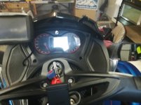
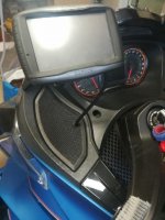
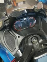
I find I don't like looking down to see the Zumo mounted on the handlebar. Looking at the 2015 ST's dashboard I noticed four bolts: two left, two right.
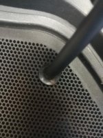
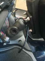
I pulled the top left bolt and the hardware store sold me a longer one with a nut and lock washer.
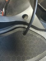
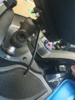
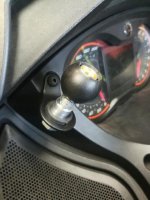
I mounted a holder for a RAM ball (Using the nut and washer to keep it at the top of the bolt and away from the dashboard plastic) and put an extension on the ball. I've ordered an AMPS compatible RAM ball and a new cradle for the Zumo.

Here's the question:

Is the bolt I'm using for the RAM holder sufficient to carry the weight of the holder, ball, arm, another ball/mount and the cradle+Zumo? It seems to me the stress is mainly to the side at the top. The bolt is fully seated and snug.

See photos.

Your wisdom/thoughts? (I had hopes of rigging up something like Lamonster sells for the RT, the bar for RAM ball mounting. Nothing for an ST: there are no places to mount it. Thought of using the bolt I used above, plus its twin on the right, and fabbing a bar to attach to both bolts, arcing the bar above the top of the dash with one RAM attached. Not sure I have the skill so to do and the question remains: are those bolts adequate?)
 

Attachments

  • IMG_20211004_154520_result.jpg
    IMG_20211004_154520_result.jpg
    33.6 KB · Views: 207
  • IMG_20211004_154713_result.jpg
    IMG_20211004_154713_result.jpg
    43.5 KB · Views: 200
I think that's brilliant. That screw isn't really taking the weight from what I can tell from your photos. I think you'll be fine. Might want to use some loctite on the threads.
 
Thanks, UtahPete. Parts are trickling in so it'll be a week or so to complete and yes: final assembly will get a little blue loctite.
(By the way. "Brown water Navy" was a new term to me, so I did some investigating. Quite a story!)
 
Thanks, UtahPete. Parts are trickling in so it'll be a week or so to complete and yes: final assembly will get a little blue loctite.
(By the way. "Brown water Navy" was a new term to me, so I did some investigating. Quite a story!)

You might want to put a spacer between the outer surface of the dashboard and the inner surface of your custom bracket, if the screw hole is recessed like on my RT.

Re: Brown water Navy; we had some really interesting and innovative fighting boats in VN. In addition to the PBRs, there were various iterations of the old landing craft (LCMs) including the 'zippo' and the 'douche' boats. Crazy.
 
I thought of adding a spacer but the nut+lock nut keep the bracket at the top of the bolt and off the plastic. The photos don't show that. I went with the nut because it was simple. Do you think a spacer would do a better job?
 
I thought of adding a spacer but the nut+lock nut keep the bracket at the top of the bolt and off the plastic. The photos don't show that. I went with the nut because it was simple. Do you think a spacer would do a better job?

I think it would provide a little more stability if the forces on the screw head were distributed over a larger area. Stacked washers should accomplish the same thing as long as they were the same hole diameter as the screw threads.
 
The project continues- - -

The screw I'm using is held by a rubber plug with a threaded brass fitting which, I believe, expands as the bolt is tightened. I guess that might distribute some stress to the surrounding plastic?

The cradle I ordered on eBay was advertised as the correct one for my Zumo. Of course it isn't. So hassles there to resolve.

Meanwhile a Question For the Group:

You can see from the photos where the GPS will be mounted. What are your suggestions on routing a power cable from the GPS into the Spyder's body where it will run to a fused connection box?

Drop it into one of the vent holes left and right? Use a bulkhead fastener (the male end is attached to, say a body panel and runs to the power source. The female end goes to the GPS. They fit together and a collar holds them in place. See an example below.

I don't want wires running every which way. I would rather not drill holes in my Spyder. The wire will carry power only; I'll not be using all the other gizmos that come with the OEM cradle. So the wires need not be too large.

So look at your dash; imagine there's a GPS at the upper left corner; now imagine how a wire should run and where it should run in order to eventually wind up connecting to a fused distribution box near the frunk.

Thanks, all, for imagining with me!
 

Attachments

  • bulkhead adapter 2.jpg
    bulkhead adapter 2.jpg
    27.9 KB · Views: 17
:popcorn:Maybe some space by the safety card pull out:dontknow: how much would have disassemble or if connector would even fit through. Still get some wind turbulence around dash (will see if caught in rain) so any loose wires will flutter, possibly rub panels or least strain solder connections.
 
Ah hah! I ignore the "safety card," never ever pulled it out except when the previous owner pointed it out, so thanks for that idea.
There IS space around the steering column; the original Zumo wire is right there. I had planned to leave the original cradle in place, but I'm debating that plan. May even pull the wiring up to see if there's sufficient length to attach to the cradle mount's new location.
Both of you provide good food for thought and I'll play around with both ideas. Thank you!

Let us know if you're able to create enough slack in the GPS cable; I'd like to do the same.

I use the card to store all my "handy" info.
20211010_141713.jpg
 
You can see from the photos where the GPS will be mounted. What are your suggestions on routing a power cable from the GPS into the Spyder's body where it will run to a fused connection box?

Cut a notch in the edge of the radio speaker grill near the mount location. It'll be hardly noticeable. That's what I did on my RT.
 
I've been eyeing the speaker grille. I have yet to even turn on the radio to see if it works and I know I'll never ride with radio blaring. Mounting a small plug/screw-through-bulkhead-gizzie along the lines of the one above (the ones I have in-hand are much smaller) would do the trick and when unplugged would appear to be small black knob or button or attachment plug. It would allow a shorter wire and would avoid dealing with friction and tension from handlebar rotation.

Hmmm. I may have just convinced myself.

The cradle arrives today (one supplier sent the wrong cradle, so I've been given another opportunity to become more virtuous by being patient.) and I'll need to do some surgery on it before mounting. Another day or two and it should be in place.

Thanks for the speaker nudge.
 
Finished!

Well, it's done and I'm happy with the way it turned out.

Rewiring the cradle was tedious but not difficult. YouTube and ADVrider have good guides.

Deciding where to put a hole in the speaker grille took a bit of time, but I'm pleased with its location.

Removing the cradle means removing the speaker grille—a simple matter—and unplugging the power cord from the two wires in the speaker cavity then threading the power cord out. I don't intend to do that very often, if at all. I'd have to remove the rubber grommet as well to pull the wire's connectors through. The grommet is not really needed and contributes only cosmetically. There's plenty of power cord in the speaker cavity to move the GPS—but I can't think of why I would.

Thanks, all, for your ideas and suggestions: much appreciated.

One of these days I'll dive underneath and remove the stock Zumo cradle mounted to the handlebars. Anyone know what tool is used to loosen those bolts? It looks like a hex head, but then again it doesn't. Can't decipher that one.
 

Attachments

  • IMG_20211019_151129_result.jpg
    IMG_20211019_151129_result.jpg
    38 KB · Views: 39
  • IMG_20211019_151204_result.jpg
    IMG_20211019_151204_result.jpg
    44.6 KB · Views: 40
  • IMG_20211019_151141_result.jpg
    IMG_20211019_151141_result.jpg
    34.6 KB · Views: 41
  • IMG_20211019_151225_result.jpg
    IMG_20211019_151225_result.jpg
    37.7 KB · Views: 50
  • IMG_20211019_151122_result.jpg
    IMG_20211019_151122_result.jpg
    34.4 KB · Views: 46
  • IMG_20211019_151156_result.jpg
    IMG_20211019_151156_result.jpg
    31.9 KB · Views: 44
Well, it's done and I'm happy with the way it turned out.

Rewiring the cradle was tedious but not difficult. YouTube and ADVrider have good guides.

Deciding where to put a hole in the speaker grille took a bit of time, but I'm pleased with its location.

Removing the cradle means removing the speaker grille—a simple matter—and unplugging the power cord from the two wires in the speaker cavity then threading the power cord out. I don't intend to do that very often, if at all. I'd have to remove the rubber grommet as well to pull the wire's connectors through. The grommet is not really needed and contributes only cosmetically. There's plenty of power cord in the speaker cavity to move the GPS—but I can't think of why I would.

Thanks, all, for your ideas and suggestions: much appreciated.

One of these days I'll dive underneath and remove the stock Zumo cradle mounted to the handlebars. Anyone know what tool is used to loosen those bolts? It looks like a hex head, but then again it doesn't. Can't decipher that one.

I'm not sure I understand how you wired up the new cradle; did you reroute the OEM cable, or just hook it up to 12vdc?
 
UtahPete—

I did some surgery on the cradle with this video as a guide: https://youtu.be/GLp3jiBS_mg

I only had to worry about two wires: 12v positive and negative. I ended up cutting the Garmin wire 16 or so inches from the cradle end, after removing it from the cradle. I pulled out all the other wires, leaving only the power leads in the black insulating cover. Since I bought a second cradle, I didn't mind butchering it. The tangle of wires that come with the cradle are now orphaned, out of the cradle, so to speak, and will be recycled for wiring other projects.

The original cradle and wiring is intact and in place; as I mentioned, I plan to remove it one day and throw it in a box on the off chance I want to restore the bike or sell the bike.

So I modified the cable AND rerouted it in order to hook it up to 12v, 12v and nothing else.
 
Columbia, was there enough slack in the OEM cable that it could have been rerouted in its entirety to the new GPS position? That's what I'd like to do.
 
That I can't say. The cable is quite long. QUITE long. I haven't tried to pull it up from the steering shaft, but I suspect that if you were to unplug the OEM cable from its many attachment points in the mess o' wires under the dash, you could easily route the whole wire loom from the GPS cradle to another location.
Bear in mind that the hole near the steering shaft is large enough to allow all the varied wire ends to fit through. (phono and USB to name a couple). So any rerouting will require a similarly large orifice for all the wires to fit through.
I don't want or need the GPS to connect via wire to a phone or the bike's radio or provide USB power to an accessory, so clipping all the extra wires, leaving only power leads, simplified things and suited my needs simultaneously.
 
Back
Top