Just curious, but has anyone found any use for this button other than for a CB. I will never use a CB. So I was thinking it would be good for a garage door opener. Don't know how to do it, wire it, or even if it's possible.
But just thought it might be a good idea.
Any Ideas ??
" Fat people are harder to kidnap "
2015 RTS-SE6 Circuit Yellow
Akrapovic Exhaust - BajaRon Sway bar
Rivco rear Trunk Rack
Lamonster LED Head Lights - LED Fog Lights
Spyder Cuff - Hwy Pegs
Ultimate Midrider Seat w/ Yellow Trim - Rear Armrests
Spyderpops Bumpskid with LED - Full view Turn Signal
R/T Front grill Inserts
3rd Brake light - Saddle bad LED
Baker Built Air Wings
Doc's Spring Stiffeners - Vibration Dampener
TRICLED underground LED'S
On previous bikes, I've run wires from a garage door opener to waterproof buttons I've installed. Now I use an app on my phone.
If you try to wire using the PTT switch, you'll have to CAREFULLY solder 2 wires to the small patterned connectors on the garage door opener circuit board. Very little copper, lots of parts that can be damaged by too much heat. Conceptually it's very easy to do.
If you look at the installation instructions for the CB module, it looks like the connector might be under the glovebox, but that's just a guess.
Just curious, but has anyone found any use for this button other than for a CB. I will never use a CB. So I was thinking it would be good for a garage door opener. Don't know how to do it, wire it, or even if it's possible.
But just thought it might be a good idea.
Any Ideas ??
Not practical. The PTT does not connect directly to any wires on the bike. The PTT button activates a contact on a printed circuit board. The circuit board is a CANBUS processor and sends a digital signal to the audio unit when you press the PTT button. If you want to do microsurgery on the circuit board you can tap into to it to connect to the switched traces on the PCB and then make use of the PTT. But if your left switch module ever craps out during the warranty period you'll most likely be out $400 since you mucked with the internals of it.
2014 Copper RTS
Tri-Axis bars, CB, BajaRon sway bar & shock adjusters, SpyderPop's Bumpskid, NBV peg brackets, LED headlights and modulator, Wolo trumpet air horns, trailer hitch, custom trailer harness, high mount turn signals, Custom Dynamics brake light, LED turn signal lights on mirrors, LED strip light for a dash light, garage door opener, LED lights in frunk, trunk, and saddlebags, RAM mounts and cradles for tablet (for GPS) and phone (for music), and Smooth Spyder belt tensioner.
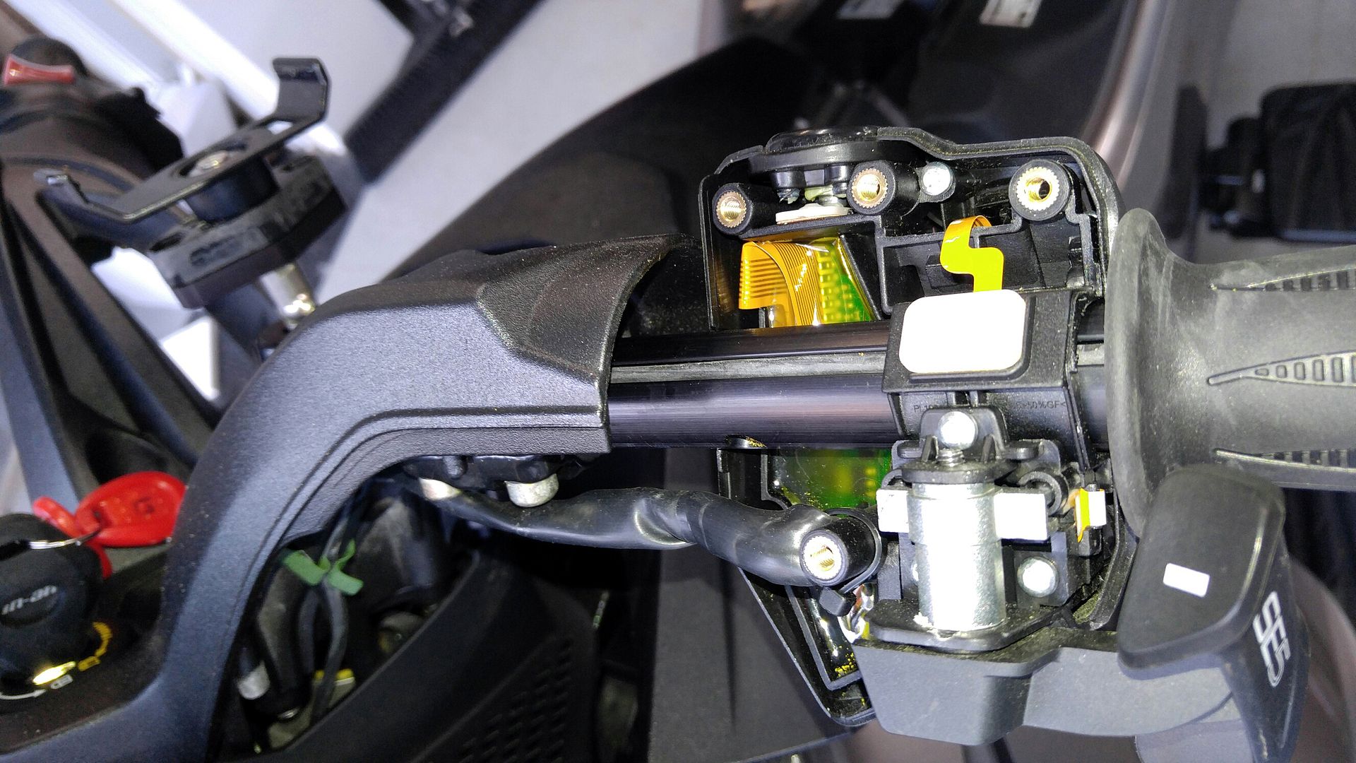
The PTT button connects to the left grip controller which is then connected to the CAN buss.
You can in fact disconnect it. It is not on a circuit board.
It has a small ribbon cable attached to it that then runs to the circuit board.
You can cut this ribbon cable and carefully solder wires to it for what you need.
I did not take this picture but this is from someone that did exactly that.
Bob
2011 RT-S SM5 - Black
Bought June 2013 with 450 miles. 27K on 8-1-2017.
Farkles - DIY Trunk Break Light, HMT Break Light, DIY Mirror Turn Signal Lights, DIY Bluetooth Dongle, DIY iPod Setup, DIY Alarm System Install, Show Chrome front fender / rear saddle bag lights, 4th break light around the trunk, Vented Windshield, Baja Ron Sway Bar, DIY GPS setup, Smooth Spyder, BRP Chrome Mirrors, Adjustable deflectors, Triaxis handlebars, NVB Pegs, Bad Boy Airhorn... More to come
The PTT button connects to the left grip controller which is then connected to the CAN buss.
You can in fact disconnect it. It is not on a circuit board.
It has a small ribbon cable attached to it that then runs to the circuit board.
You can cut this ribbon cable and carefully solder wires to it for what you need.
I did not take this picture but this is from someone that did exactly that.
Bob
]
I stand corrected.
Sent from my SM-T350 using Tapatalk
2014 Copper RTS
Tri-Axis bars, CB, BajaRon sway bar & shock adjusters, SpyderPop's Bumpskid, NBV peg brackets, LED headlights and modulator, Wolo trumpet air horns, trailer hitch, custom trailer harness, high mount turn signals, Custom Dynamics brake light, LED turn signal lights on mirrors, LED strip light for a dash light, garage door opener, LED lights in frunk, trunk, and saddlebags, RAM mounts and cradles for tablet (for GPS) and phone (for music), and Smooth Spyder belt tensioner.
I figured it wouldn't be as easy as I had hoped for....thanks for the discussion !
" Fat people are harder to kidnap "
2015 RTS-SE6 Circuit Yellow
Akrapovic Exhaust - BajaRon Sway bar
Rivco rear Trunk Rack
Lamonster LED Head Lights - LED Fog Lights
Spyder Cuff - Hwy Pegs
Ultimate Midrider Seat w/ Yellow Trim - Rear Armrests
Spyderpops Bumpskid with LED - Full view Turn Signal
R/T Front grill Inserts
3rd Brake light - Saddle bad LED
Baker Built Air Wings
Doc's Spring Stiffeners - Vibration Dampener
TRICLED underground LED'S
The PTT button connects to the left grip controller which is then connected to the CAN buss.
You can in fact disconnect it. It is not on a circuit board.
It has a small ribbon cable attached to it that then runs to the circuit board.
You can cut this ribbon cable and carefully solder wires to it for what you need.
I did not take this picture but this is from someone that did exactly that.
My project this weekend is to swap the PTT and HORN buttons. I am constantly hitting the horn button in the stock location and cant find it when I do need it. If I put it where the PTT button is, I will have no trouble finding it. Hoping its a straight forward swap.
Most likely not. At least you shouldn't try to swap the functions of each to the other button. The horn button handles up to 10 amps or so. The PTT button handles milliamps at best. Running the horn circuit through the PTT button will undoubtedly burn up the PTT button contacts. Swapping the physical buttons may be a possibility but it would most likely require a lot of physical alteration of the switch assembly.
2014 Copper RTS
Tri-Axis bars, CB, BajaRon sway bar & shock adjusters, SpyderPop's Bumpskid, NBV peg brackets, LED headlights and modulator, Wolo trumpet air horns, trailer hitch, custom trailer harness, high mount turn signals, Custom Dynamics brake light, LED turn signal lights on mirrors, LED strip light for a dash light, garage door opener, LED lights in frunk, trunk, and saddlebags, RAM mounts and cradles for tablet (for GPS) and phone (for music), and Smooth Spyder belt tensioner.
Most likely not. At least you shouldn't try to swap the functions of each to the other button. The horn button handles up to 10 amps or so. The PTT button handles milliamps at best. Running the horn circuit through the PTT button will undoubtedly burn up the PTT button contacts. Swapping the physical buttons may be a possibility but it would most likely require a lot of physical alteration of the switch assembly.
I'm certaily not an auto electrician, but i would think that if the PTT button only activated a relay the difference in amperage should not be a concern, or am i being to simplistic.
I'm certaily not an auto electrician, but i would think that if the PTT button only activated a relay the difference in amperage should not be a concern, or am i being to simplistic.
If that is the case, it would just be a signal voltage, no problem.
I'm certaily not an auto electrician, but i would think that if the PTT button only activated a relay the difference in amperage should not be a concern, or am i being to simplistic.
Just make sure the relay has a low pull-in current load. Even then it might be a bit high for the PTT since all it does is close a circuit on a printed circuit board. You could try it and see what happens.
2014 Copper RTS
Tri-Axis bars, CB, BajaRon sway bar & shock adjusters, SpyderPop's Bumpskid, NBV peg brackets, LED headlights and modulator, Wolo trumpet air horns, trailer hitch, custom trailer harness, high mount turn signals, Custom Dynamics brake light, LED turn signal lights on mirrors, LED strip light for a dash light, garage door opener, LED lights in frunk, trunk, and saddlebags, RAM mounts and cradles for tablet (for GPS) and phone (for music), and Smooth Spyder belt tensioner.
I studied the wiring diagram but the PTT circuit is not on it. I was hoping to just swap the switch locations, but that might not be possible. I will keep working on it. If I figure out a way, I will let you know. Why cant they make it a simple switch.
It's not on the wiring diagram since it does not connect to anything on the wiring diagram. It's in the table below the wiring diagram for all the switch functions of the left multi-switch that are part of the CANbus processor. All the controls of the radio are CANbus signals.
2014 Copper RTS
Tri-Axis bars, CB, BajaRon sway bar & shock adjusters, SpyderPop's Bumpskid, NBV peg brackets, LED headlights and modulator, Wolo trumpet air horns, trailer hitch, custom trailer harness, high mount turn signals, Custom Dynamics brake light, LED turn signal lights on mirrors, LED strip light for a dash light, garage door opener, LED lights in frunk, trunk, and saddlebags, RAM mounts and cradles for tablet (for GPS) and phone (for music), and Smooth Spyder belt tensioner.
you seem to know about this stuff. I just got a sena 50 r thinking on getting the cb radio adapter. I want to hook up my cb on the bike to it. can it be done
Although it's an old thread it may be useful to somebody; this can be done, I've done a few non OEM cb installs. Your soldering needs to be very good! The ribbon cable can be cut and the surface plastic scraped away to reveal the copper tracks. The problem is that one track is very thin and fragile and it will break off if the soldered wire is pulled, even lightly. The solution is to solder a very light wire to the tracks - I use fuse wire - then trap the soldered joint between two small pieces of rubber - superglue the rubber pieces and bring them together around the soldered joint taking care not to glue your fingers to the whole thing! Once this is done you can now solder fine cables the the fuse wire tails. Take the small cables and glue them to somewhere convenient to anchor them. Once you've done that you can route the cables out of the handle bars. If your cable is sizeable you may need to make a small notch in the edge of the plastic so as not to pinch the cable as the switch assembly is tightened closed.
In my case I use the PTT switch to ground a cable from a relay coil so the relay caries the active load for whatever device I switch using the PTT button.
Rule#2: Never argue with an idiot. He'll drag you down to his level & then beat you with experience.
Rule#1: Refer to rule #2.


 Reply With Quote


 I bought the Limited; thinking that it had that...