As I have asked many question regarding the Customer Accessory Circuits and how to install a GPS, I thought I would just do it. So, this is how I did the install of a Garmin 595LM (the up to date version of the 590 which is sold by BRP).
I used a handlebar mount, all included with the Garmin except for the long reach RAM Long Double Socket Arm (6"). I mounted the primary attachment using the bolts supplied and attaching it to the base of the left hand Grip/Handlebar clamp. The 6" arm attaches to this, and the Garmin mount for the 595LM, to the top of the arm.
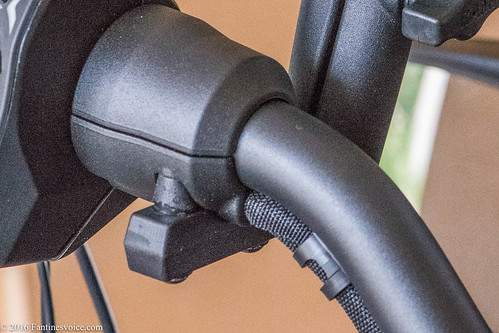
The wiring is the most interesting as I could not identify the middle Customer Accessory Circuit wires until I had removed the left side panel. Then one can see the friction tapped wires hanging down, and once the tape is removed, gosh there they are, a black ground and purple/white hot wire (Hot when engine is running). Here is a photo showing the wire after I placed shrink tubing on the end of the remaining friction tape so as to keep it from unraveling. Zumo 595LM Installation_09.11.2016_TFL-2 by Tommie Lauer, on Flickr
Look carefully and you will see the purple/white hot wire and all the connections.
So, what does one do with the huge amount of wires from the Garmin mount? I simply folded them up and tucked them away, Zip tying to a part of the roadster. I did not want to cut any of these at this time. Zumo 595LM Installation_09.11.2016_TFL-7 by Tommie Lauer, on Flickr
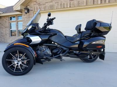
After all is said and done, the cable from the Garmin mount zip tied in place so as to avoid any chafing when the handlebars are moved, I mounted the Garmin and it actually worked. Zumo 595LM Installation_09.11.2016_TFL-8 by Tommie Lauer, on Flickr
Oh, on the handlebar mount some small shaving of the pacers from Garmin was necessary, but no issue for those who do this stuff on a regular basis.
If any questions .... let 'em rip.
Msmoto
2016 F3 Limited SS, Garmin 595LM, Sena 10S, Belt Idler Pulley, Custom Cherry Bomb Exhaust
Previous Spyder No. 003008
As I have asked many question regarding the Customer Accessory Circuits and how to install a GPS, I thought I would just do it. So, this is how I did the install of a Garmin 595LM (the up to date version of the 590 which is sold by BRP).
I used a handlebar mount, all included with the Garmin except for the long reach RAM Long Double Socket Arm (6"). I mounted the primary attachment using the bolts supplied and attaching it to the base of the left hand Grip/Handlebar clamp. The 6" arm attaches to this, and the Garmin mount for the 595LM, to the top of the arm.
The wiring is the most interesting as I could not identify the middle Customer Accessory Circuit wires until I had removed the left side panel. Then one can see the friction tapped wires hanging down, and once the tape is removed, gosh there they are, a black ground and purple/white hot wire (Hot when engine is running). Here is a photo showing the wire after I placed shrink tubing on the end of the remaining friction tape so as to keep it from unraveling. Zumo 595LM Installation_09.11.2016_TFL-2 by Tommie Lauer, on Flickr
Look carefully and you will see the purple/white hot wire and all the connections.
So, what does one do with the huge amount of wires from the Garmin mount? I simply folded them up and tucked them away, Zip tying to a part of the roadster. I did not want to cut any of these at this time. Zumo 595LM Installation_09.11.2016_TFL-7 by Tommie Lauer, on Flickr
After all is said and done, the cable from the Garmin mount zip tied in place so as to avoid any chafing when the handlebars are moved, I mounted the Garmin and it actually worked. Zumo 595LM Installation_09.11.2016_TFL-8 by Tommie Lauer, on Flickr
Oh, on the handlebar mount some small shaving of the pacers from Garmin was necessary, but no issue for those who do this stuff on a regular basis.
If any questions .... let 'em rip.
That ram ball mount under the cuff.... I know the part #... But I don't think it comes with spacers?... Or does it? I thought of doing the same thing... I did buy a clutch mount ball instead for now.
WackyDan - Fun, not crazy.
Charlotte (Matthews), NC Silver Moon SM5 - V35 and V46 Givis, CHAD, Motolight 35w steering lights, Dash Powerlets, Helibar risers, Garage door opener, Eastern Beaver PC-8, Digital voltmeter, Kewl Metal Intake, Evoluzione Sway Bar, RT Shocks and Juice Box PRO. *Mower deck in development*
2008 model -new in crate, April 09
26,000 miles.
Looking for other Charlotte area riders to cruise with and compare Spyders.
The RAM ball mount under the cuff comes with spacers from Garmin. However, these require a small amount of shaving down the diameter (I did a conical shave using a grinder and the spacer on a round shaft) then they will fit nicely into the recess in the cuff. If you look carefully at the spacers, you will see how they are cut down in a conical shape.
Now, the 6" long arm is something one must purchase from RAM. And, I may change this to a two piece extension so as to be able to rotate the Garmin clockwise and avoid the reflection from my high visibility riding suits... makes seeing the Garmin more difficult in the sunlight.
Msmoto
2016 F3 Limited SS, Garmin 595LM, Sena 10S, Belt Idler Pulley, Custom Cherry Bomb Exhaust
Previous Spyder No. 003008
I just installed the Garmin Zumo 660LM. I already had the Lamonster F3 Top handlebar clamp. I added Lamonster's GPS swivel mount and moved my phone up to next to the left control with a Lamonster control RAM ball mount. I wired mine down the right side and to the rear auxiliary port under the seat. I plan to install fog lights and heated grips later.
Very nice job, guess I will make a trip to NC to visit you for installation.
Joe
U.S. Army Viet Nam Era Vet
2013 Spyder RT-L, Black Currant
Trunk mount dual SS flag holder
TricLed foam hand grips (awesome)
Chromed Soaring Eagle License Holder
Utopia Deluxe driver backrest
LED fender lighting
Fast Flash LED brake light
Spyder Pops LED/skid plate
Resurrecting this thread, please. I just ordered a Garmin 595L and the F3 swivel mount from Lamonster. Looking at this thread confuses me just a little. The OP attached to the customer accessory circuits via the "hanging" black/purple-white wires. But later in the thread someone asks where the "stock GPS connector is"....are these the same thing, or is there some type of modular connector used for the "stock GPS connector" via the Garmin 590L/595L?
We usually have dealers wire our GPS mobile systems since it usually involves (in the case of Harley Davidson), plugging into an ignition circuit at the fuse location, and Jeff is not interested in going there, simple as it might be. But reading this post, it appears the wires and/or connector are already there, so he thinks he will tackle it himself.
thanks.
Carolyn
In one of the Lamonster videos, I can't remember which one at this time, he actually point it out. I will see if I can remember which video.Here is my Lamonster swivel mount with the Dual power mounts for my 595.


Zumo 595LM Installation_09.11.2016_TFL-2 by Tommie Lauer, on Flickr
Zumo 595LM Installation_09.11.2016_TFL-6 by Tommie Lauer, on Flickr
Zumo 595LM Installation_09.11.2016_TFL-7 by Tommie Lauer, on Flickr
Zumo 595LM Installation_09.11.2016_TFL-8 by Tommie Lauer, on Flickr

 Reply With Quote

 , the other 3 connections only power up after the motor is running.
 2016 F3T Magnesium Metalic : Smooth Spyder Dual Backrest, Lamonster LED Head lights and Fog lights
