There is a space on the left side of the RT under the fascia trim which turns out to be perfect for mounting a 139dB Stebel Nautilus Dual-tone Air Horn.
For reasons not explained, the manufacturer would like the Nautilus to stand vertical side-to-side and fore-and-aft. The space I've chosen for this will acommodate the Nautilus as near perfectly upright as makes no difference!
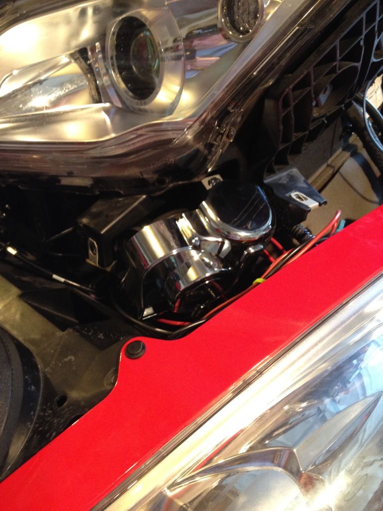
Photo #1 shows the Nautilus. The yellow arrow points to a small cutout I made to the upper horn to allow it to slot around the left bracket. (See arrow in photo #4 for where this fits). The bright metal piece sticking up and out to the right of the horn is the mounting bracket I made out of aluminium.
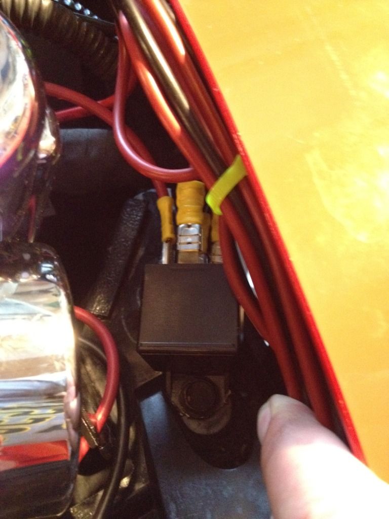
Photo #2 shows the aluminium bracket holding the Nautilus in position. The bracket has to be cut as shown in photo #1 to allow the RT's fascia to be fastened in place. A hole has to to drilled into the projecting fascia support to allow a bolt through for the bracket and the relay.
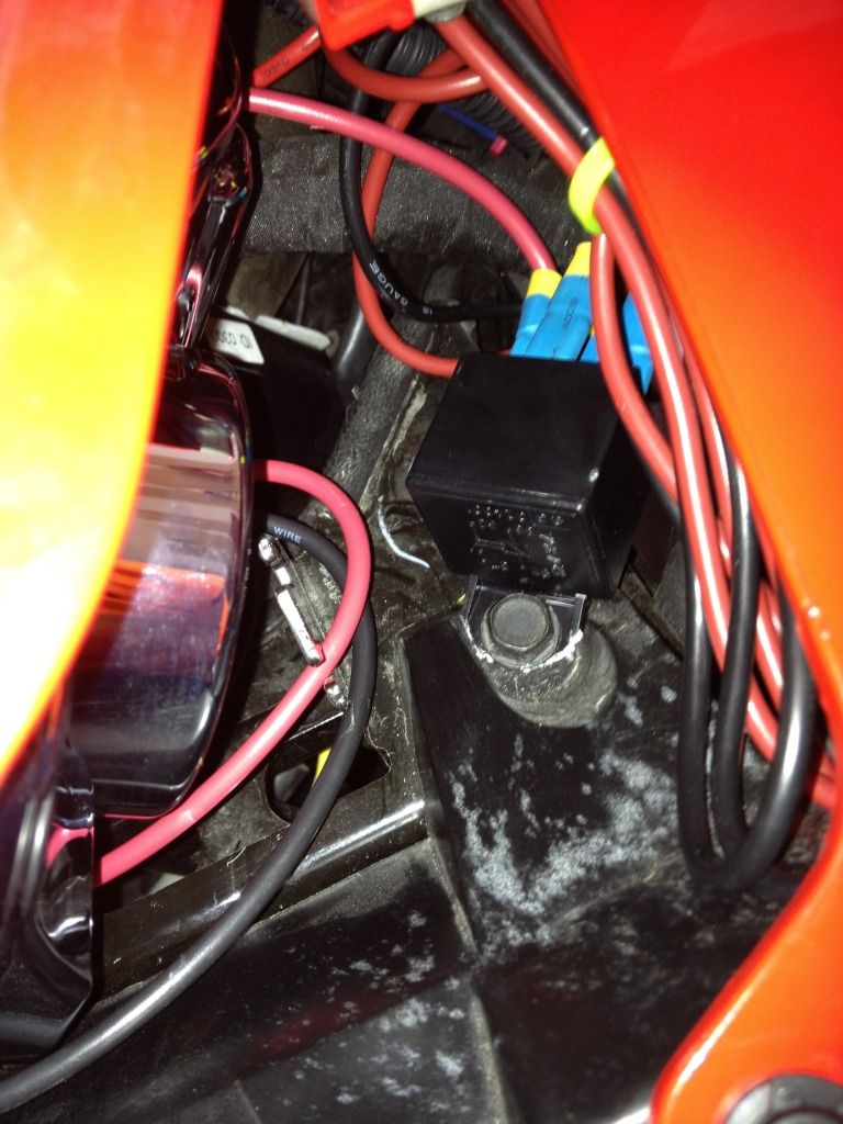
Photo #3 Shows the Nautilus in position. Note the 2 blue Positaps taking the horn push wires to the relay. The RT's wire colors are Blue/beige (+) and Green/grey (-). Using a relay, (supplied with the Nautilus), to connect a 20amp supply direct from the battery is the prefered option. The wiring for the RT's existing horn is insufficient for prolonged use of the Stebel. For full volume output the horn manufacturer recommends a dedicated 20 amp supply.
Photo #4 shows the location I used. There are a pair of BRP brackets, (color-washed yellow), which it seems are not used for anything at all. The yellow arrow shows where the cut-out I made in the plastic of the upper Nautilus horn in photo #1 slots onto the bracket.
Look out for a further post from me on this installation dated 04-28-2013. Heading: Stebel Nautilus Horn Mount VIBRATION PROBLEM and CURE
Last edited by GeoffCee; 10-16-2014 at 07:58 PM.
Reason: modification
2011 RT-S SE5, Acumen Tempest Cat-1 Alarm, SmoothSpyder Belt Tensioner,
Autocom Super Pro Auto, Garmin Zumo 550 BT, 10amp Socket, Front Fender LED's,
Grip Puppies, Spyderpop Belt Guard, Nautilus Horn, Shortee Antenna, BajaRon's Swaybar,
Cree LED Day Running Lights.
Great install .I bought the Stebal about 6 weeks ago and tried to install it where the old stock horn was and I couldn't make it work as others have so I just put it on my work bench and I'll give it another try on a rainy day. Your install is perfect and it looks pretty simple.
A few questions -did you put a 20 amp inline fuse in after the relay wired directly to the battery and did you use the wires from the stock horn to the relay and then new wire to the battery ? Did you remove the old horn ?
Thanks. I left the old horn in place, it's doing no harm.
Yes, there is a 20 amp in-line fuse from the battery to the relay and I used the existing horn wires to trigger the relay.
I have a dedicated 25 amp wire from the horn (-) connector to the (-) negative side of the battery.
2011 RT-S SE5, Acumen Tempest Cat-1 Alarm, SmoothSpyder Belt Tensioner,
Autocom Super Pro Auto, Garmin Zumo 550 BT, 10amp Socket, Front Fender LED's,
Grip Puppies, Spyderpop Belt Guard, Nautilus Horn, Shortee Antenna, BajaRon's Swaybar,
Cree LED Day Running Lights.
Very nice install - neat and tidy - Professional IMHO
Geoff as a matter of intrest I have posted a reply ref the Brackets - See your earlier thread
I have fitted the Stebel Nautilus Air Horn in the same location as the stock horn although mine sits on its side due to lack of space - as yet no issues
I have fitted an additional Fusebox where the Brackets are located and they help to secure it
It would have been interesting to find out what those Brackets were intended for, or maybe they were used in the assembly process to assist with lifting etc
We may never know
Well Done
Eddie Sheppard
Reading UK
Spyder RT-S SES (AUTO 2010 Model)
List of Mods :-
Added Zuno 660 -Garmin kit as supplied on the Spyder RT Limited
Digital Voltmeter and Digital Clock to replace Fuel and Temp gauge Fuel and Temp now
displayed in Cluster Display
LED Bulbs Reversing Lights,Front position lights
HMT - Brake Light
LED Running lights
LED - Mud Flap lights
Rear extended Mud Flap
Sport Tall Wide Clear Windshield
Utopia Backrest
S/S Grills both sides matching
Bottom Panel S/S Protection
S/S stronger Funk Lid brackets
S/S Bracket for RBNS Hood for Zumo 660 GPS + TourTech Lockable Mount
Rubber Tank protector on glove box
Grip Puppies
Power Socket in Switch Cluster and at Rear passenger Handrail
Rear Speaker Switch for passenger On/OFF
Upgraded Front Marine Speakers
Bluetooth On board Radio to Sena SMH10 Headsets
I have fitted the Stebel Nautilus Air Horn in the same location as the stock horn although mine sits on its side due to lack of space - as yet no issues
I have been searching for the reason that Stebel want their Nautilus mounted vertically, just out of interest, but I have been unable to find out why this is so. On a variety of motorcycle and vehicle websites there are plenty of examples available of the Nautilus being mounted in a variety of positions, and when space is tight the horn often ends up way off the vertical, as yours is. In the main this manufacture's requirement is being largely ignored, nevertheless the Nautilus appears well thought of by those who have bought it. It sure is LOUD!
Last edited by GeoffCee; 08-28-2011 at 09:23 PM.
2011 RT-S SE5, Acumen Tempest Cat-1 Alarm, SmoothSpyder Belt Tensioner,
Autocom Super Pro Auto, Garmin Zumo 550 BT, 10amp Socket, Front Fender LED's,
Grip Puppies, Spyderpop Belt Guard, Nautilus Horn, Shortee Antenna, BajaRon's Swaybar,
Cree LED Day Running Lights.
If I remember correctly, the Nautilus is "weatherproof" if it is mounted vertically, so it can drain instead of collect water. If it's protected, it should be okay.
You didn't happen to make a template of that bracket did you or know the dimensions? I have have to mount the Stebel on the wifes Spyder and this is just the info I was looking for. Great write up.
Sent from my DROIDX using Tapatalk
2007 M109R LE - To many MODS to list. Its cheaper that way!!!
You didn't happen to make a template of that bracket did you or know the dimensions? I have have to mount the Stebel on the wifes Spyder and this is just the info I was looking for. Great write up.
Thanks. Template? No, but I can talk you through what you need to do.
Get a piece of thin metal, in my case it was a piece of stiff aluminium strip left over from another project. It was an offcut, an inch wide, about 7" long and 1/8" thick. I drilled a hole in one end to take the fixing bolt supplied with the Nautilus, pushed the bolt through and finger-tightened the retaining nut.
The next thing is to drill a hole in the plastic support (see photo) but you'll need to decide on a bolt diameter first. The bolt should be long enough (see Note below) to fasten the metal strip securely and also have enough thread left over to also mount the relay -- you can see this arrangement in the photos. The bolt doesn't need to be more than about 1/4" in diameter, drilling a larger bolt hole could weaken the plastic.
Note: The relay needs to be brought forward about 1/4" so its contact spigots underneath clear the Spyder's wiring loom. That is why there is one nut holding the bracket in place and another one fastening the relay. (See photos). This is the reason for using a long bolt.
When you've decided on a suitable bolt, drill a hole for it in the plastic support piece, under where one of the fairing mounting screws is located, (see photo). When you've drilled this hole, manouver the Nautilus into position and hold it there. Rotate the metal strip (like the hand on a clock face) until it covers the hole and scribe through from the back of the hole to leave a mark on the metal. This marks the position for a hole in the metal strip for the fixing bolt.
Push the bolt, together with a washer, through the hole in the plastic, fasten it lightly on the mounting bracket and adjust the position of the Nautilus, so that it is sitting vertically. Then tighten up the nuts on both bolts.
As well as the mounting bracket you have made, the horn needs to be supported at its other end. That is the purpose of the notch, or cutout, in the upper horn (there are two horns, an upper and a lower). The cutout allows the Nautilus to "sit" further forward on the left-hand bracket. You can mark where the notch needs to be with the aid of a torch and a metal scribe. I used a hacksaw blade to mark its position in the soft plastic. A cutout depth of about 3/8" will do for this.
Oh, and finally, you'll need to cut off the excess length of bracket metal at the right hand side. You'll end up with a shaped end, something like my example in the photos.
Last edited by GeoffCee; 08-31-2011 at 05:41 AM.
Reason: clarification
2011 RT-S SE5, Acumen Tempest Cat-1 Alarm, SmoothSpyder Belt Tensioner,
Autocom Super Pro Auto, Garmin Zumo 550 BT, 10amp Socket, Front Fender LED's,
Grip Puppies, Spyderpop Belt Guard, Nautilus Horn, Shortee Antenna, BajaRon's Swaybar,
Cree LED Day Running Lights.
Thanks. Template? No, but I can talk you through what you need to do.
Get a piece of thin metal, in my case it was a piece of stiff aluminium strip left over from another project. It was an offcut, an inch wide, about 7" long and 3/16" thick. I drilled a hole in one end to take the fixing bolt supplied with the Nautilus, pushed the bolt through and finger-tightened the retaining nut.
The next thing is to drill a hole in the plastic support (see photo) but you'll need to decide on a bolt diameter first. The bolt should be long enough to fasten the metal strip securely and also have enough thread left over to mount the relay -- you can see this arrangement in the photos. The bolt doesn't need to be more than about 1/4" in diameter, a larger bolt hole could weaken the plastic.
When you've found a suitable bolt, drill a hole for it in the plastic support piece, under where one of the fairing mounting screws is located, (see photo). When you've drilled this hole, manouver the Nautilus into its final position and hold it there. Rotate the metal strip (like the hand on a clock face) until it covers the hole and scribe through from the back of the hole to leave a mark on the metal. This is where you will drill a hole in the metal bar for the fixing bolt.
Push the bolt, together with a washer, through the hole in the plastic, screw it up tight on the mounting bar and adjust the position of the Nautilus. Then tighten both bolts.
As well as the mounting bar you have made, the horn needs some additional support to take its weight at the other end and that is why I made a notch in the upper horn (there are two horns, an upper and a lower) to allow the Nautilus to "sit" better on the left-hand bracket. You can mark where the notch needs to be with the aid of a torch and a metal scribe.
Oh, and you'll have to cut off the excess length of the bar. You'll end up with something shaped like the example in the photos.
Thank you, I will adding this on the wifes Spyder in the next couple of weeks. As soon as I get the time to tear it apart. I have the horn sitting on my workbench waiting. I am a helicopter mechanic by trade, electrician I am not. Anything that isn't plug and play electrically always worries me and on the Spyder will all of the electrical stuff on it worries me more an my 9. That and because if I screw it up, I'll hear it from the wife. Its not like when I screw stuff up on my 9.
Thanks again,
Shane
2007 M109R LE - To many MODS to list. Its cheaper that way!!!
If I remember correctly, the Nautilus is "weatherproof" if it is mounted vertically, so it can drain instead of collect water. If it's protected, it should be okay.
john
Thanks. That makes sense. It's a good product, so what puzzles me is why Stebel don't better explain the whys and wherefores.
2011 RT-S SE5, Acumen Tempest Cat-1 Alarm, SmoothSpyder Belt Tensioner,
Autocom Super Pro Auto, Garmin Zumo 550 BT, 10amp Socket, Front Fender LED's,
Grip Puppies, Spyderpop Belt Guard, Nautilus Horn, Shortee Antenna, BajaRon's Swaybar,
Cree LED Day Running Lights.
I am a helicopter mechanic by trade, electrician I am not. Anything that isn't plug and play electrically always worries me and on the Spyder will all of the electrical stuff on it worries me more an my 9.
I am not an electrician, either, but I know my way around wiring up the Nautilus, having just been through a steep learning curve with it. If you get nervous but don't mind an amateur's approach to electrics, drop me an e-mail when the time comes, I'd be happy to give you all my expertise -- it won't take more than a minute of your time.
2011 RT-S SE5, Acumen Tempest Cat-1 Alarm, SmoothSpyder Belt Tensioner,
Autocom Super Pro Auto, Garmin Zumo 550 BT, 10amp Socket, Front Fender LED's,
Grip Puppies, Spyderpop Belt Guard, Nautilus Horn, Shortee Antenna, BajaRon's Swaybar,
Cree LED Day Running Lights.
I am not an electrician, either, but I know my way around wiring up the Nautilus, having just been through a steep learning curve with it. If you get nervous but don't mind an amateur's approach to electrics, drop me an e-mail when the time comes, I'd be happy to give you all my expertise -- it won't take more than a minute of your time.
I will do that, thanks.
Sent from my DROIDX using Tapatalk
2007 M109R LE - To many MODS to list. Its cheaper that way!!!
My question to you is: the wires in pic 3, are they the wires from the stock horn and were they right there where you have them connected to the relay or did you have to fish them from elsewhere. I have the same horn but very little electrical knowledge, then how did you run the + wire to the Batt., and can I ground to any bolt or do I have to run that to the Batt. also? Thank you for your help!!
Originally Posted by GeoffCee
There is a space on the left side of the RT under the fascia trim which turns out to be perfect for mounting a 139dB Stebel Nautilus Dual-tone Air Horn.
For reasons not explained, the manufacturer would like the Nautilus to stand vertical side-to-side and fore-and-aft. The space I've chosen for this will acommodate the Nautilus as near perfectly upright as makes no difference!
Photo #1 shows the Nautilus. The yellow arrow points to a small cutout I made to the upper horn to allow it to slot around the left bracket. (See arrow in photo #4 for where this fits). The bright metal piece sticking up and out to the right of the horn is the mounting bracket I made out of aluminium.
Photo #2 shows the aluminium bracket holding the Nautilus in position. The bracket has to be cut as shown in photo #1 to allow the RT's fascia to be fastened in place. A hole has to to drilled into the projecting fascia support to allow a bolt through for the bracket and the relay.
Photo #3 Shows the Nautilus in position. Note the 2 blue Positaps taking the horn push wires to the relay. The RT's wire colors are Blue/beige (+) and Green/grey (-). Using a relay, (supplied with the Nautilus), to connect a 20amp supply direct from the battery is the prefered option. The wiring for the RT's existing horn is insufficient for prolonged use of the Stebel. For full volume output the horn manufacturer recommends a dedicated 20 amp supply.
Photo #4 shows the location I used. There are a pair of BRP brackets, (color-washed yellow), which it seems are not used for anything at all. The yellow arrow shows where the cut-out I made in the plastic of the upper Nautilus horn in photo #1 slots onto the bracket.
I have been searching for the reason that Stebel want their Nautilus mounted vertically, just out of interest, but I have been unable to find out why this is so. On a variety of motorcycle and vehicle websites there are plenty of examples available of the Nautilus being mounted in a variety of positions, and when space is tight the horn often ends up way off the vertical, as yours is. In the main this manufacture's requirement is being largely ignored, nevertheless the Nautilus appears well thought of by those who have bought it. It sure is LOUD!
If the unit is mounted upright, the piston inside the air pump is more reliable.
If you lay it on its side, the piston wears more on one side and fails prematurely.
If it ain't broke, don't break it.
IBA #47122
2020 RT Limited Asphalt Grey
If the unit is mounted upright, the piston inside the air pump is more reliable.
If you lay it on its side, the piston wears more on one side and fails prematurely.
I'm happy there is a mechanical reason.
Premature failure is a bad thing. It happens before you expect it, that's for sure.
2011 RT-S SE5, Acumen Tempest Cat-1 Alarm, SmoothSpyder Belt Tensioner,
Autocom Super Pro Auto, Garmin Zumo 550 BT, 10amp Socket, Front Fender LED's,
Grip Puppies, Spyderpop Belt Guard, Nautilus Horn, Shortee Antenna, BajaRon's Swaybar,
Cree LED Day Running Lights.
My question to you is: the wires in pic 3, are they the wires from the stock horn and were they right there where you have them connected to the relay or did you have to fish them from elsewhere. I have the same horn but very little electrical knowledge, then how did you run the + wire to the Batt., and can I ground to any bolt or do I have to run that to the Batt. also? Thank you for your help!!
The wires from the stock horn are conveniently located pretty much where you see them in the photo - no fishing required! I found it an easy matter to run the ground wire from the Nautilus back to the battery where there is already a reliable grounding stud on the metal structure of the petrol tank.
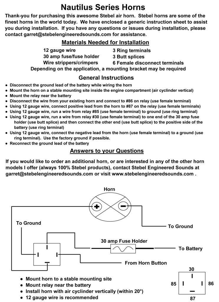
Wiring the Nautilus
Starting with the basics, the relay supplied with the Stebel Nautilus horn is a solenoid-activated switch. Typically, a relay uses a low power circuit to control a high power circuit. The two circuits are separate and are wired through the relay separately.
The low power circuit for the relay already exists on the Spyder - it is the circuit which operates the stock horn when the horn button is pressed. Using Positaps to break into this will provide the relay's switching circuit with power. In addition to the Positaps you will also need a pair of insulated push-on connectors at the relay end.
The high power circuit is the one you have to introduce yourself using wires which are capable of carrying 25 amps. The Nautilus horn consumes about 18 amps, so a 25 amp wire provides a necessary safety margin. (Pushing high amperage down a wire which is not capable of carrying it will heat up the wire, destroy the insulation and it becomes a potential fire risk).
You will need two lengths of wire for this, I suggest red to supply a circuit from the battery (+) to the relay and black to connect an earth wire from the Nautilus (-) connector to the earthing point. You will also need high amperage push-on connectors at the relay end and also for the Nautilus's connections, an in-line fuse rated at 20 amps and a pair of insulated ring terminals to connect to the battery (+) and the earthing stud (-). I would recommend soldering your connectors, crimping is a poor substitute for solder unless carried out with professional crimping tools.
The relay's terminals are numbered. The numbering system used derives from German auto construction practices introduced many decades ago, but as obscure as this may seem today it remains a recognised standard of identifying which relay connections are which.
Terminals #85 and #86 are the low power switching circuit. Connect the Spyder's stock horn switch wires here. Terminal #85 conventionally goes to earth (-) but it will work either way round. When you press the horn switch on the handlebar it will send power through a solenoid inside the relay and activate (close) the high-power circuit.
Terminals #87 and #30 are the high power connections. Connect the (red) battery lead, which carries an in-line 20 amp fuse, to terminal #30. Connect relay terminal #87 to the Nautilus (+) connector.
Connect the Nautilus (-) connector to the battery earthing point with (black) 25 amp wire.
That's it. Tidy up the wiring and the job is done!
2011 RT-S SE5, Acumen Tempest Cat-1 Alarm, SmoothSpyder Belt Tensioner,
Autocom Super Pro Auto, Garmin Zumo 550 BT, 10amp Socket, Front Fender LED's,
Grip Puppies, Spyderpop Belt Guard, Nautilus Horn, Shortee Antenna, BajaRon's Swaybar,
Cree LED Day Running Lights.
Whew, what an experience! Of all the electrical mods that I've done, this has been the most aggravating. Installing the Stebel Nautilus in an RTS (with fog lights) is like putting 10 lbs. of potatoes in a 5 lb. sack. My install and GeoffCee's install are night and day apart. My install had a few more obstacles due to other electronics that I had already installed in the same area. Primarily, my power supply and receiver for my remote under lighting which, was installed where the Stebel should go.
My stock horn had two leads and plugs going to the horn, not one. There was a red+ and a black- plug. I had to reach in through the wheel well to reach these and pull them off of the horn. Removing the three push pins from the fascia that surrounds the fog light (the ones that are visible when the frunk lid is open) will allow you to use a coat hanger to pull the wires up in order to wield your magic. You'll only have about 2 or 3 inches of wire to work with. I cut the plugs off and spliced 12 gauge extensions on to them in order to reach the area where the Stebel will be mounted.
I did not pull the frunk for this mod. It's such a tight fit that I recommend that you don't pull the frunk. With the frunk still in place you know just how much room you have to work with. As mentioned before, I have other stuff in this area. The only way that I could make this horn fit within the 20° from vertical stance, that is recommended by the manufacturer, was to use 3M Double Sticky Velcro. By attaching the horn at two points with velcro, it is vibration resistant and firmly attached. Also, I rotated the horn so that the horn openings faced the honey combed air vent, which allows for more sound to emanate. it's loud and it's awesome!
Mounting the relay:
There are 4 bolts that attach the frunk at the top. I cut the corners off of the relay mounting tab, so that I could bolt it to the far right frunk bolt (as you are in front of the bike looking at it).
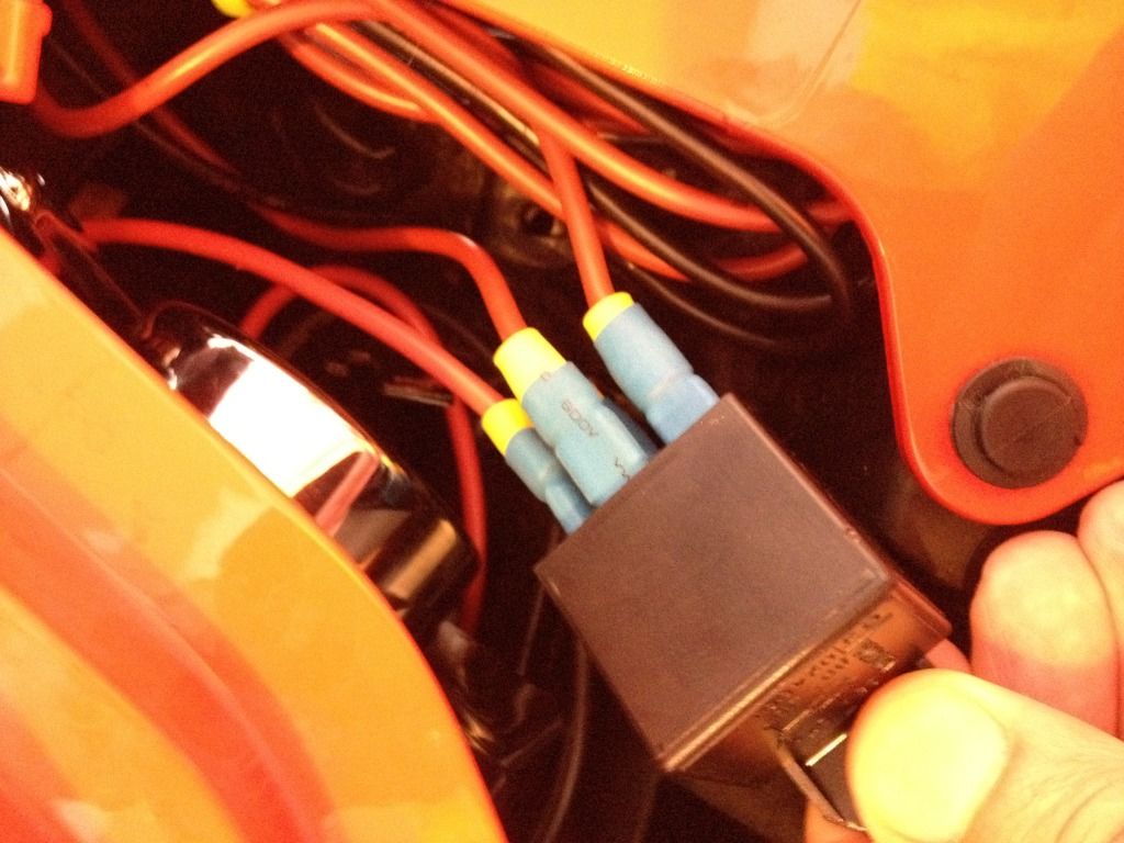
GeoffCee had noticed that I had left my relay tabs without anything protecting them from a short. Fortunately, the location that I installed the relay at allowed me to just pull the black accessory panel in order to remove it and apply heat shrink tubing over the connections. Thanks for the suggestion, Geoff!
This is a poor picture, but you get the idea.
You have to pull several panels off of the bike to do this. If you are thinking of installing a horn that gets attention and you've never taken any panels off, then check out Lamont's video on removing panels.
To add insult to injury, after 6 hours of doing this install... once all the panels were back on, I had a screw left over. I'm pretty sure where I left one out and it's not critical. I'll put it back in the next time I have to pull almost all of the panels off.
The following two pics are from Stebel on wiring diagrams. If you aren't comfy with doing you're own electrical work on the Spyder, these diagrams should help you to decide if you're capable of this or not. I wish you luck and much patience.
A side note:
The inline fuse circuit that I had run from the battery to my under lighting only had a 3A fuse in it. To keep from running another inline fuse for the Stebel, I placed a 30A where the 3A was and cut the + line and pigtailed another inline fuse with the 3A just before the under lighting PSU and after the Stebel + line.
Last edited by kevorama; 09-02-2012 at 12:22 PM.
Dream as if you'll live forever, live as if you'll die tomorrow.
―James Dean
Looking at the photo of your relay I would suggest you put some insulating tape or heat-shrink sleeving around the exposed metal on the relay's push-on connectors. You have a 30 amp fused open circuit to the battery on at least one of those push-ons. Better safe than sorry.
Geoff, I couldn't agree more. I don't know why I didn't do that while it was still easily accessible. Hopefully, my location of the relay will allow me to access it with only the removal of the accessory cover. I'll post the new pic, provided I can get to it today. Thanks for the heads up!
Dream as if you'll live forever, live as if you'll die tomorrow.
―James Dean


Stebel Nautilus Horn Mount VIBRATION PROBLEM and CURE


 Reply With Quote
 Great install .I bought the Stebal about 6 weeks ago and tried to install it where the old stock horn was and I couldn't make it work as others have so I just put it on my work bench and I'll give it another try on a rainy day. Your install is perfect and it looks pretty simple.
  Happy
Happy  Owner
Owner