Completed: Below this is a comparison of the different light sources I'm working with. This upgrade will be both a headlight upgrade and an aux light upgrade, and as usual for me will cost a third of commercially available products and be demonstrably better. Follow the thread to the end for current before and after pics.
tl/dr. I installed Bi-Xenon HIDs where the factory aux lights go using factory wiring and not cutting anything or affecting the warranty.
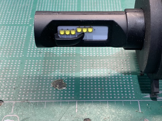
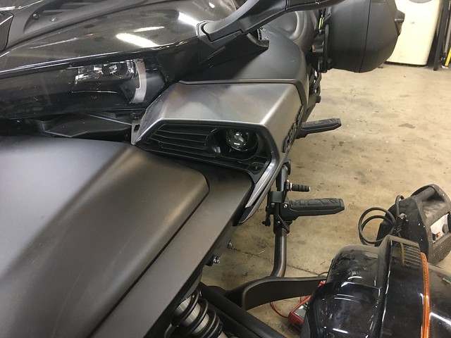
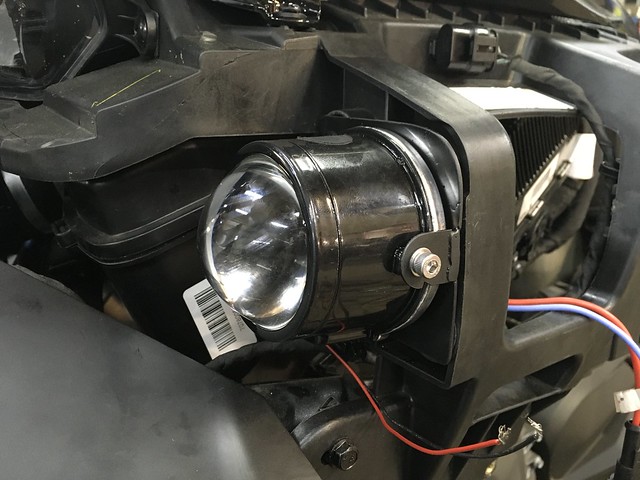
Now for the fun bit. New aux beam low. This is sitting on my bench hooked to a 12v battery. Please also note that this is a single unit, I'm installing a pair.
As said I'm waiting on parts, but when I'm finished this will be a direct drop-in (with some fabbing of mounts) with no wires cut and all stock looking.
2019 F3S SM6 , Black metallic with pearl color change
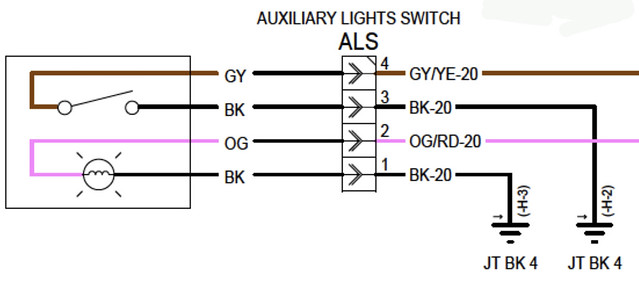
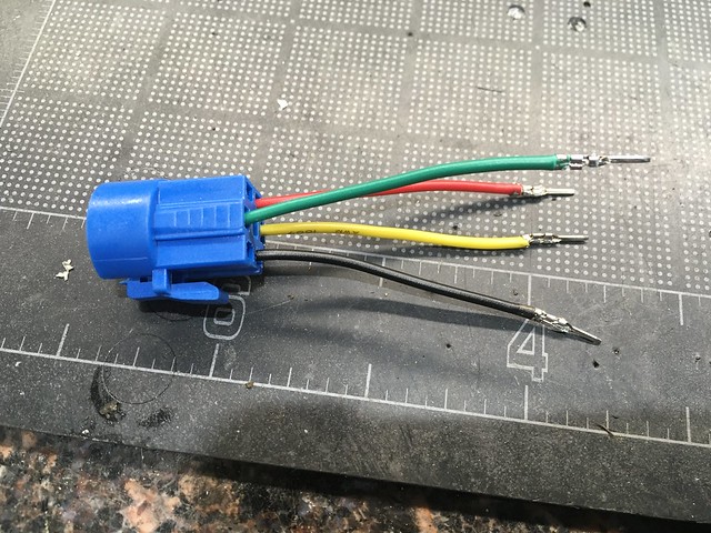
The connector for the stock switch is not available separately from can-am that I'm aware of, and costs about $9 on the ebays. The manufacturer is printed right on the connector, and a bit of confuser gargling managed to get me the part numbers for all the connectors. I was able to make 5 complete sets (of which I only need half of one set) for about $15 so now I have extras. Also Digikey ships really fast.
The pins that this connector use require a special crimper that I thought I had. Turns out mine is way too big, so I had to improvise. I used my crimper to do the majority of the work, then did a little massaging with small pliers to get the crimp down to the right size to fit in the housing. It didn't help that the insulation on the wires I used was larger than it liked. BTW that's a 1" grid on the mat behind it to give a sense of scale. I have enormous bear paws for hands so handling tiny delicate stuff isn't my strength.
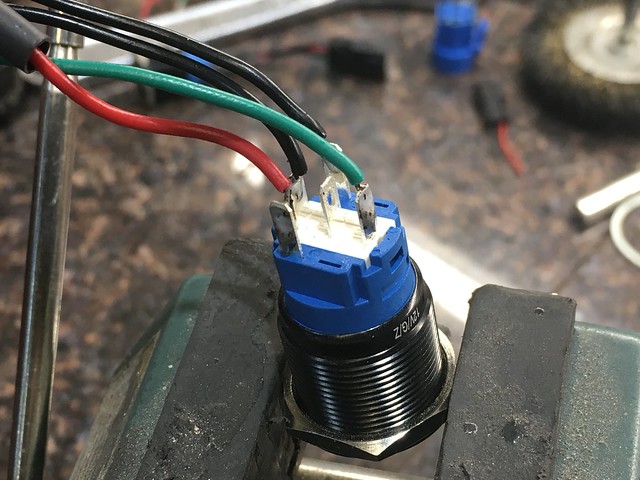
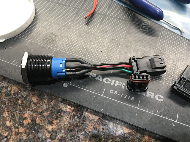
The switches I bought came with a connector. I depinned the unused wire. The switch has - and + for the light, common, normally open and normally closed.
Since I had extra switches and extra connectors, I figured I'd get them set up too. These I decided to wire directly to the switch, as it seemed excessive to have a connector 3" away from another connector.
Then I installed the switch. This caused me no end of trouble because I put it on the left side, as is good and proper. After all, that's the side where the light switches are, right? Lots of troubleshooting later I finally realized that the factory put the heated grip on that side, and the aux lights on the other side. Pulled the connector across and voila! everything works. Anyway I also drilled a very small hole in the plastic to drain water, it seemed like a bad idea to put a switch in a shallow bowl with no drain.
Then I made a couple of these. They're just under an inch wide, just over half an inch tall, have a 1/4" hole through, and have a quarter inch knocked off the side.
Then I made these mounts. They were quite the evolution, but they're made from some leftover steel I had from taking some old computer stuff apart plus some bolts.
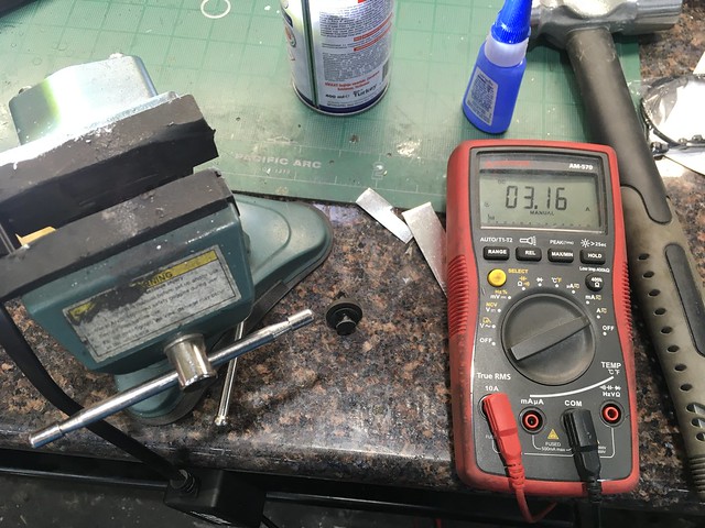
They were a pain because there's about 3.16" available to work with behind where the light blank goes, and my lights are about 3". My son who knows about such things said I'd be better off putting the glass lenses behind some polycarbonate, so they had to mount way back.
Speaking of polycarbonate, I had some on hand that even had UV coating so I decided to go ahead and get the lenses cut out. One of my rolls of electrical tape was just the right size so I used that as a template. To make a hole for the lens I used some step drills to remove most of the middle then a series around the outside edge.
Then I glued the lenses in from the back using some seat repair glue, which is actually some pretty strong polyurethane adhesive, that has no problem sticking to both the polycarb and the plastic the housing is made of.
2019 F3S SM6 , Black metallic with pearl color change
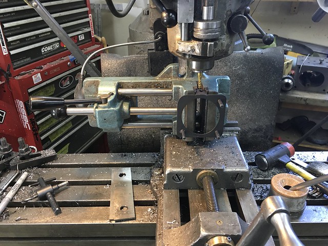
Gluing the lenses in was a total failure. The glue I used let go of the housing with very small pressure. I peeled all of it off, tested two different types of plastic epoxy (which both failed) and switched to Lexel, which if you believe the label will glue anything from wood to jello. We'll see. Then I did some more work on the right side mount, needed to adjust the slots for the projector mount. Fully sketchy here, I needed height so I clamped my drill press vise in my mill vise then clamped the mount in the drill press vise. Worked though.
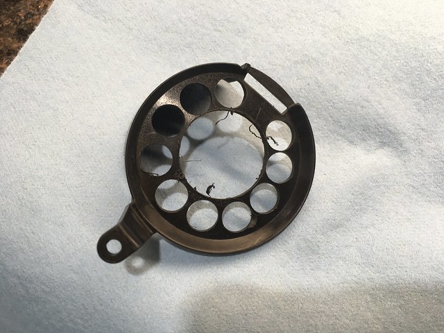
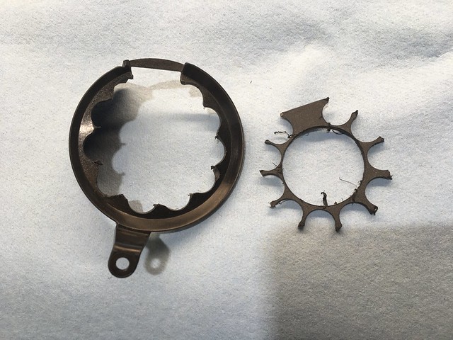
I didn't mention before, but I'm sure you already figured out I'm using some bi-xenon projectors. Had to file off the rear mounts to get it to fit close enough.
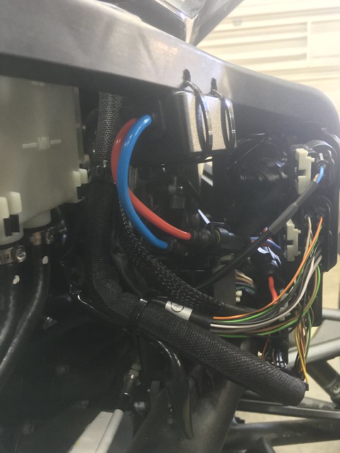
Bi-Xenons default to low beam. When power is applied to a solenoid it switches to high beam. The stock wiring for aux lights on the bike only provides power, no low/hi signal so I had to make some t-harnesses to get that high-beam signal. I used some cheap headlight extensions that I added wire to, fused at 2a, then the other end uses another can-am style 2-pin connector.
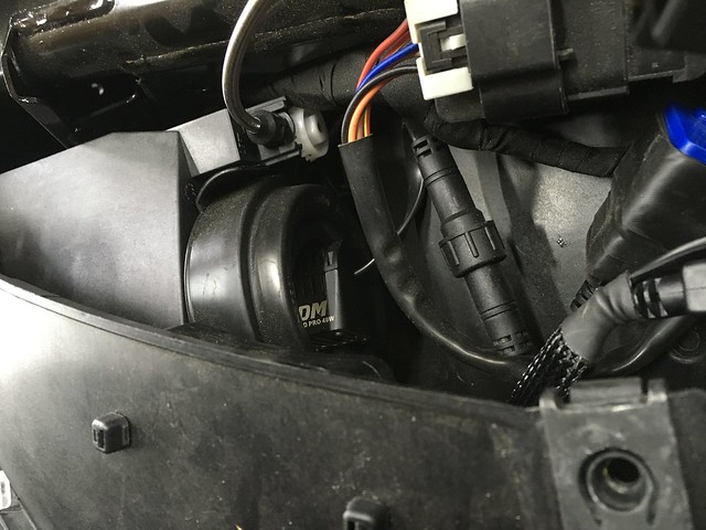
I added the t-harness inline, and sealed the connections using self-vulcanizing tape. This shows the other upgrade I did, adding some DDM Tuning 40w LED bulbs in the stock locations. You've already seen the pictures of the upgraded beam. These headlights use a separate power supply inline with the bulb, which I installed upside down hanging from the plastic. You can see the two holes I drilled to support the zip ties that hold it up.
I now have one side almost completely installed, the other is waiting for paint to dry. I ordered some tessa tape from the amazons which should arrive tomorrow so I can match the stock wiring. So far I'm pretty pleased with how this is working out, although it's a lot more work than most people would be willing to do vs. just installing a set of direct-fit LEDs. But when I'm done I'll have a lot more light than most, and it still won't have modified the actual bike in any way or touched my warranty. Plus the total for the whole thing (minus my time) will still be under $150, which is about half what just the other LED bulb-LED aux light cost.
These rated as some of the brightest of the LED bulb replacements in a few tests, and honestly the bike has a 90 amp alternator so saving power isn't a priority. According to DDM (so take it with a grain of salt) they produce 9000 lumens per pair.
2019 F3S SM6 , Black metallic with pearl color change
Finished! The last few bits I was waiting on arrived so I got everything buttoned up. First pics show the t-harnesses in place, with the connections sealed up with self vulcanizing rubber tape. Forgot to mention, the Lexel adhesive is awesome. Messy to work with but it seemed to have no problem adhering to the lens or the shroud.
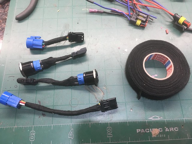
Next shows the before and after for my switch harnesses. I had an extra switch connector so I built a longer harness for it to account for having the switch on the opposite side than factory. That's the Tesa tape, it's the same kind of fabric backed tape used by the factory to loom smaller wires together.
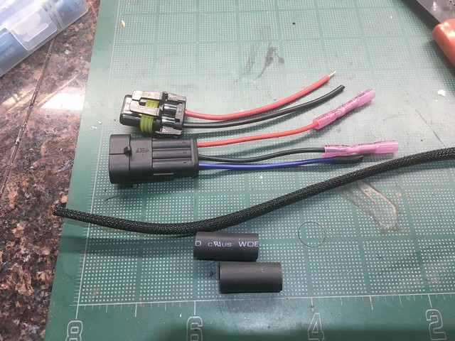
Next shows the parts I used to make the final jumper that connects between the bike and the HID power supply. I clearly intended to take an after picture but got excitedand installed them, so just imagine all those put together.
I did some testing because I had to wait on the parts. The hottest part of the housing gets to just over 200*, and the ballast gets to just over a hundred. Assuming the shroud around the light is made of PA6 FRP, it's well below the 250*f continuous rating. Assuming it's some other thermoset FRP the safety margin is larger, and it doesn't actually touch any of the plastic anyhow.
Right now I have them aimed so the low beam cutoff is 26" unladen, and 28" when I'm on the bike. Not sure where they should be, but that seems to be pretty much just below level from the projectors, and puts the high beam hot spot right where the LEDs do. I'll try to get some night pics tonight, but those are always a crapshoot with a phone camera that automatically adjusts itself as needed to whatever light it has available. Overall pleased with myself on this project.
2019 F3S SM6 , Black metallic with pearl color change
Just a suggestion. Get a relay either timed or manual to turn on the HID’s. Ballast’s and bulbs do not like being turned on and off quickly. Also, ballasts draw more power at start up (at least they used to). I’ve retrofitted HID’s on 3 of my Sportbikes, a car, and my truck, and the relays would let the bikes start up, then the HID’s would start up 2-5 seconds later. This allows the battery to fully dedicate power to starting the bike, then the ballasts can start with full system power. The Sportbikes headlights would come on with the key turned to ACC power, then turn off real quick when the ignition switch engaged, then headlights would turn back on. That’s a no bueno for HID’s and ballasts in regards to longevity.
Nice. If you want your switches to only be lit when the lights are on, you will need to cut the hot to the switch's light ring and run a wire to and from the +12v at the light if you are using the OEM circuit.
Not sure of your age, but as time passes... If you put out too much light up there, road signs, road markings and reflectors may feed too much light back at you causing too much contrast. High contrast between these reflective surfaces and the non-reflective things that you need to see (like that raccoon) might make the real hazards dangerously dim to your eyes. This indeed could be worse than having not enough light up there to begin with and is especially true with "older" eyes. Just a thot.
As far as aimimg. You want the cutoff line of the low beam no higher than the mirror height of oncoming traffic. Other than that youll find the sweet spot between visibility close and far away. Too high, and there will be a dark area right in front of you, and too low...well you wont be able to see. This video pretty much sums it up.https://youtu.be/03fHzDEHVV4
What projectors are you using? The aux’s seem to fit perfectly in the stock mounting holes. I’ve been thinking of retrofitting the Spyder as well, but haven’t gotten into researching projectors that will fit into the headlight housing, or the aux light holes. You might actually find that the Aux projectors will be more than sufficient with visibility, that you may not need to worry about the headlights. Unless of course you want the power of the sun.
The stock aux light circuit is powered by the load shedding circuit, so it doesn't get power until the bike is running. So even if I leave the switch on, it still waits till the bike is on before it gets power.
Thanks, I'm aware of how to make the light come on when the light is on. (edit: that sounded rude. Sorry, didn't mean it that way) The easier way to do it would be to take + from the stock wire, and use the output from the switch to provide a switched -. I haven't decided yet whether or not I want it, and may in fact get my son to make me a fancy PWM so that the light's dim when the bike gives it power and full power when I have the switch on. Baby steps. Good info though. The factory uses the switch to provide negative to the aux light relay, so if you give the button light power as intended but give it negative from the output of the switch it'll only light up when the switch is on.
I fully know the problem of having too much light aimed wrong, I've had Lasik twice. That's why I want so much *controlled* light. That's why I was unhappy with the thought of the stock or aftermarket aux lights; every pic I've seen of them show what they look like from the front, not what kind of beam pattern and light output they create. I know the bi-xenon provides a very controlled, very bright light.
For aiming I measured the low beam cutoff directly in front of the projectors, and they measured right at 28". I figure that as long as I stay below that line, the light will never rise into someone else's eyes, and if your eyes are 28" or less from the road surface then my headlights are the least of your problems. By aiming them just less than 28" they must be less than parallel from the ground and shouldn't blind anyone. That said I made them adjustable, so no harm no foul if I need to change it in the future.
I hate to say, but I don't exactly know what projectors I'm using. I bought a set of sealed, waterproof (that's the hard and important part; most projectors are designed to live inside another sealed headlight housing) projectors off of ebay. The seller contacted me after a month and said they were out of that one, and could he send me a different one? I said sure, and that's what arrived. So no, I'm honestly not entirely sure what they are.
My LED headlight bulbs are supposed to be good for 9000 raw lumens. The 35w HIDs should be good for another 6000 or so, vs the stock 800 or so estimated H4 lumens. Yes I'm going for the light of the sun. I'm considering swapping my 40w LEDs into the wife's bike, and getting myself a set of 55W LEDs that should be good for 12500 lumens. I can always turn lights off as needed, but the roads I enjoy, and the crap quality of my eyes make bright, controlled light very important.
BTW special thanks to Rattlebars! Your heads up on the GPS wiring connectors on Amazon are what led directly to me doing this. Once I had the link to the 2-pin, it was simple like pie to find the rest of the connectors. The way I did all of this, there is no cutting of wires, no significant modification of the stock bike, and the total actual change to the bike is just a couple holes drilled for zip ties.
2019 F3S SM6 , Black metallic with pearl color change
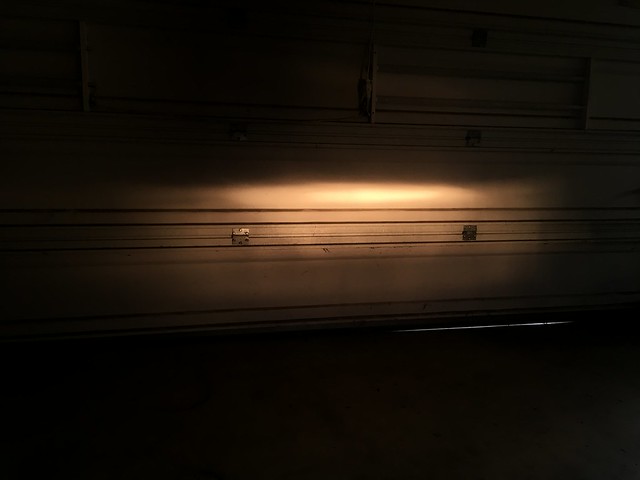
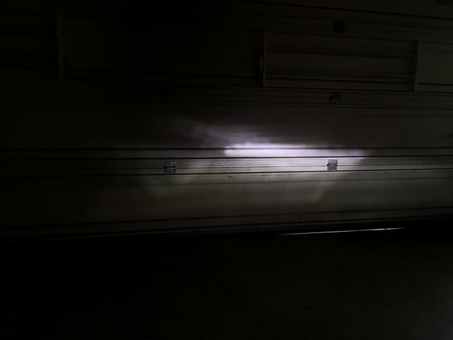
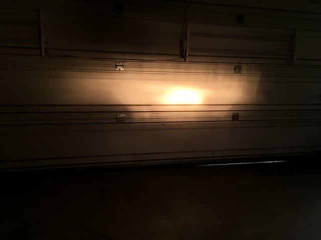
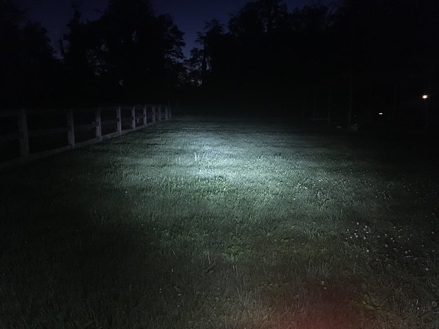
Ok, it finally got dark enough to do direct comparisons. Conditions: Dark. Ipad set on autofocus/autoexposure lock. Stock Ryker with dual H4 headlights equivalent to stock spyder. Spyder with upgraded LED headlight bulbs, spyder with upgraded LED headlight bulbs and HIDs both low and high beams. First, low beam stock, LED, and LED plus HID. Note in these that the Ryker has an aux light that splashes the ground directly in front of the bike with light so it seems brighter directly in front, but look further out and you can't see my fence or any of the trees.
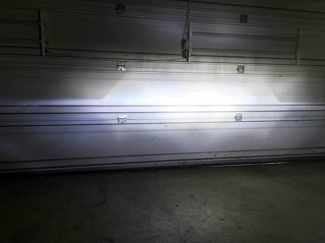
Now the high beams. Same deal, ryker with aux lights, spyder with LED, and spyder with LED and HID. My wife helped take the pics and gently hinted that I needed to fix her headlights because she could barely tell any difference between high and low beam on her bike and mine looked like a plane landing.
Thanks! It was only a lot of work because I wanted it to be. I could recreate it in pretty short order if I had to. I'm just fussy, and bored, and have a lot of tools available to play with. I honestly don't understand why the usual suspects don't offer this as a kit. It's manufacturing cost can't be more than the LED, the only extra parts are the T-harnesses to grab high-beam and figuring out where to mount the ballast.
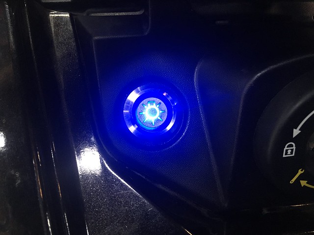
As rattlebars pointed out, there are a few ways to wire the switch. I have available blue and green power symbols, and I just ordered a red fog lights and a blue headlights symbol button. The headlights one came in so I wired it up with a spare connector and wired it so it only lights up when the button is depressed.
The bad thing about this switch is that one of the pins is turned 90* compared to my other ones, so I can't just reuse the same harness and swap the switches out as I please. The good thing about it is that there's some internal leakage in the switch or the wiring harness for the bike, so when the bike gets power it lights the switch very dimly. Goes to full bright when it's on. Sweet, no need for a fancy PWM setup.
Love it. I really enjoy your posts as I mentioned before. Unfortunately I cannot ride at night much anymore so my setup which uses 4 x 10W led projectors is all I can manage to tolerate. Total cost roughly $30. Note that I don't post in these threads because I am in competition with the OP or anyone else. I post only to add information to an already good thread by offering alternatives and or more info. My budget is limited and my tool set is as well. I try to do things that pretty much anyone can do.
No worries, I welcome all ways of doing stuff. As I said, I've had lasik twice and my eyes are crap, so I try not to ride at night at all. However, guaranteed that if I get caught out it'll be in bad weather on a back road with poor markings and no moon. So I figure I'll stack the deck in my favor, while trying to keep everything OEM looking.
2019 F3S SM6 , Black metallic with pearl color change
Looks good! None of what I've done has been for people to see me, it's all for me to see them (although if I hit high beams it's definitely an attention grabber). I'm planning the back of the bike now, and that's going to all be about seeing me.
2019 F3S SM6 , Black metallic with pearl color change
That’s a valid point. I haven’t gotten to there yet, but I will be adding some dazzle to the front for left turner avoidance. I just haven’t decided exactly what yet. My buddy came over for (awesome) steak the other day and we did a direct comparison of his lights vs mine. No question mine are better, but I have to say the CanAm aux lights are pretty well controlled, albeit not very bright.
2019 F3S SM6
2019 F3S SM6 , Black metallic with pearl color change
Final(ish) update. You'all better appreciate this, I was swapping lights and bulbs all afternoon to get you comparison pics. Ok, so when last we left our intrepid explorer I had ordered some DDM Tuning Saber ProX 55w LEDs to replace my 40w by the same manufacturer. The whole ordering process was sketchy, and they apparently rode the slow boat from china (literally) and just arrived. So I figured I'd go ahead and swap them out. First I decided to measure the current draw so I could figure out the watts, simple enough. Volts times amps equals watts. They were advertised as a 55w bulb. At 12.5v (my test battery) that should equal 4.4 amps. Nope, they were less than three. Hmm, let me run it a while and warm up the bulb. Highest I saw it draw was 3.1a, for 38w. I was ready to go into a full on rage. Also on the old bulb both low and high lit on high, on these only the respective emitters lit up.
I was raging. 3.16a! Where are my watts! Anyway I figured I was already this far in may as well install one so I could do a comparison. Then I figured If I was doing that I'd pop a halogen back in so I could show you back to back comparison pics. As per usual all pics were taken with my ipad because it's easier to upload pics to Flickr from that. Autofocus/autoexposure was disabled, and were set against the barn door with the lights on for a standard of reference. Then lights were turned off and each bulb tested in turn.
They may need adjusted, the halogens seemed a bit higher than the LEDs but I'm going to run with it for now and see how it does. The 40W LEDs go into the wife's Ryker.
Last edited by whodat; 06-30-2020 at 07:31 PM.
Reason: sspeeling
2019 F3S SM6
2019 F3S SM6 , Black metallic with pearl color change
Total side note. On the F3 there's a small panel under the driver's seat that's held on by a clip and a push-pin. BRP isn't very good at building these things, and they put an undersized push pin in with a rubber washer to try to take up the space. They fall out every time I take the side panels off. I bought a 200piece assortment of push pins, and went one size up and it fits perfectly. Why they couldn't have done this from the factory I don't know.


Untitled by Uncle Grr!, on Flickr
Untitled by Uncle Grr!, on Flickr
Untitled by Uncle Grr!, on Flickr
Untitled by Uncle Grr!, on Flickr
Untitled by Uncle Grr!, on Flickr
Untitled by Uncle Grr!, on Flickr

 Reply With Quote


 to see my 2016 F3-T and many how to's


 Good job, casts a nice light down road!!! looks like a lot of work