|
-
 Installing the PowerSportsWrap GS/RS/RS-S Dash Kit Installing the PowerSportsWrap GS/RS/RS-S Dash Kit
Installation:
The installation instructions provided with the kit are excellent and they provide all the general information necessary for proper installation. However some areas require extra care to ensure a proper fit. The following are additional instructions for those specific areas.
The importance of test fitting each part is key. The installer should be very familiar with the exact fit of each part before removing the protective backing. Use care not to apply 3M Adhesive Promoter to any section of the dash that will not be covered by a part as staining may occur.
Here are all the included parts:
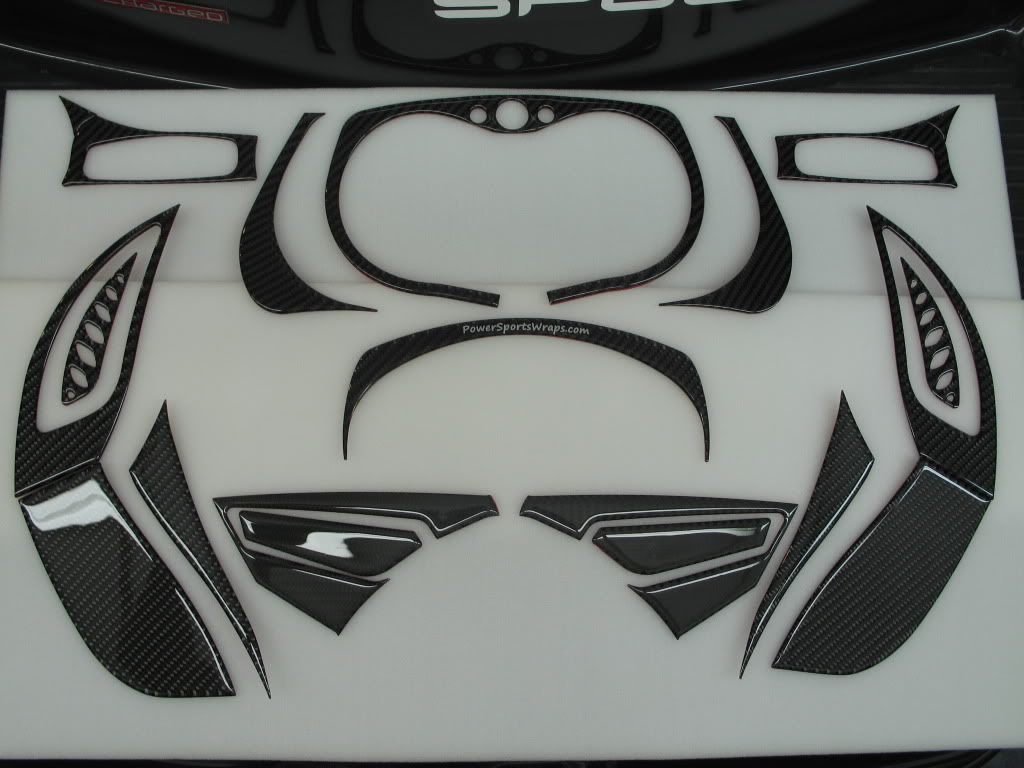
If you have installed any switches, lights, power outlets, etc. on sections to be covered by the Dash Kit you can easily drill through the kit material
using ordinary drill bits. The dash material is very easy to cut and offers no resistance. It has the consistency of soft plastic.
I would offer the following drilling suggestions:
- Ensure the drill bit is reasonably sharp.
- Carefully mark the location of the existing hole. You can do this by careful measurement or imprinting the location of the hole
on the part. I usually place a little colored grease around the hole then carefully place the part on top of it. If done properly
the grease will mark the exact location of the hole on the part.
-Start with a very small pilot hole.
-If drilling a large hole work your way up to the full size by drilling a succession of smaller holes.
-Place a block of scrap wood underneath the material for support and to ensure a clean cut.
4612-05 Part-5:
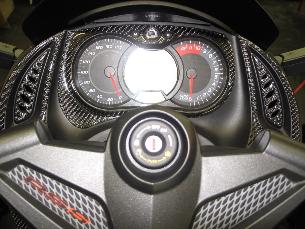
The Display Console on a GS/RS Spyder is easily user removable. Instructions to do this are included in the BRP owner's manual as it is necessary to remove it to change the headlight bulbs.
It is much easier to apply 4612-05 Part-5 with the display console removed:
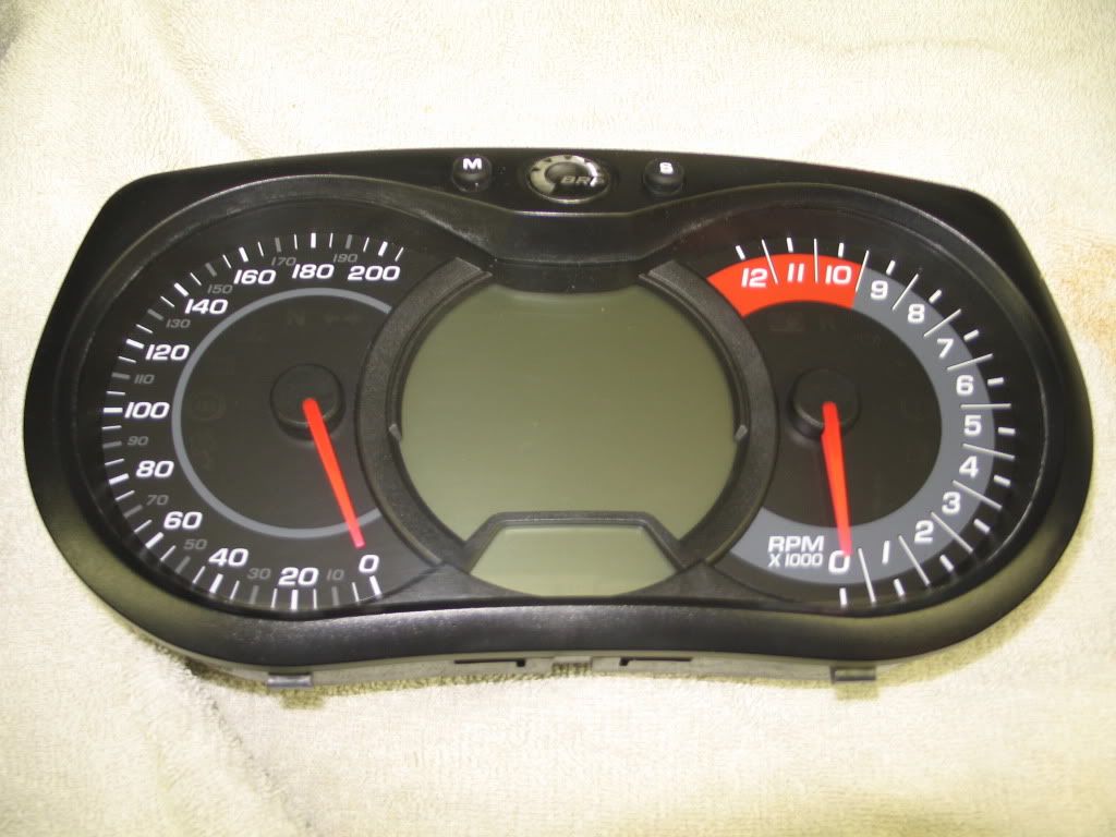
However this is not required and the part can be installed with the display in place. Installation of Part-5 should begin at the BRP logo and button area.
Peel away only enough of the protective backing to carefully center the part over the logo and buttons:
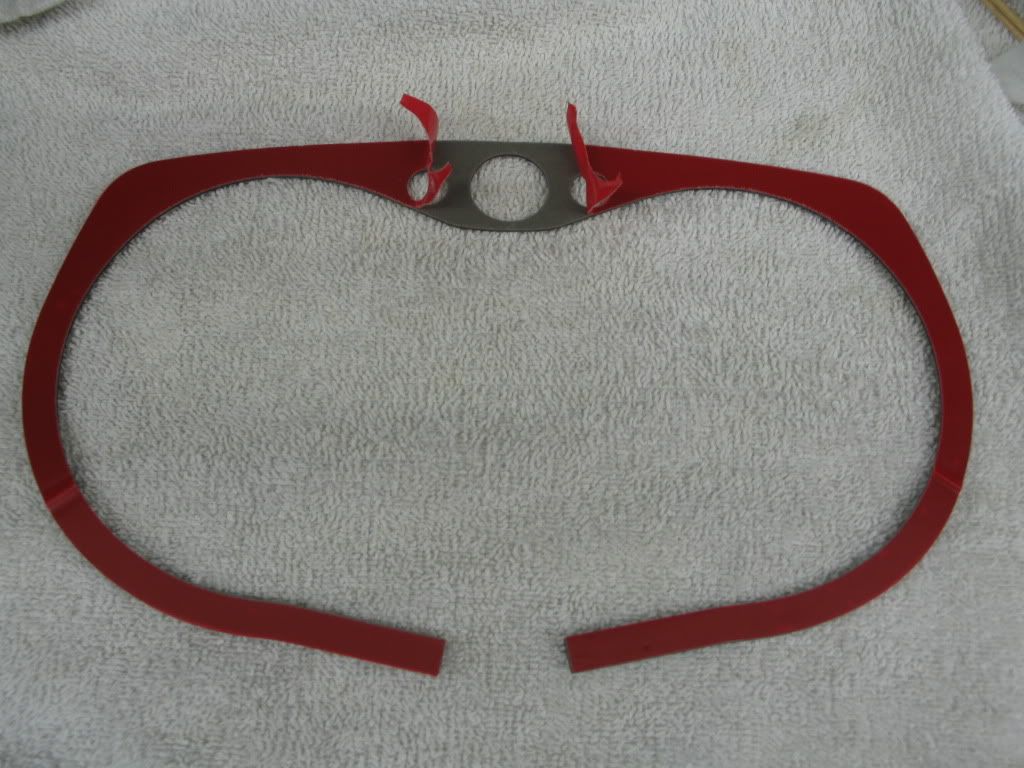
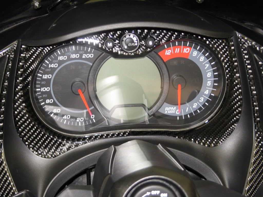
Then, gradually pull away the protective backing on the left side only carefully centering the part until the entire left side is adhered.
Next remove the protective backing from the lower section of the right side only and adhere the right half next to the left half.
Then, gradually removing the backing as you go, adhere the remaining section moving upward toward the top of the display.
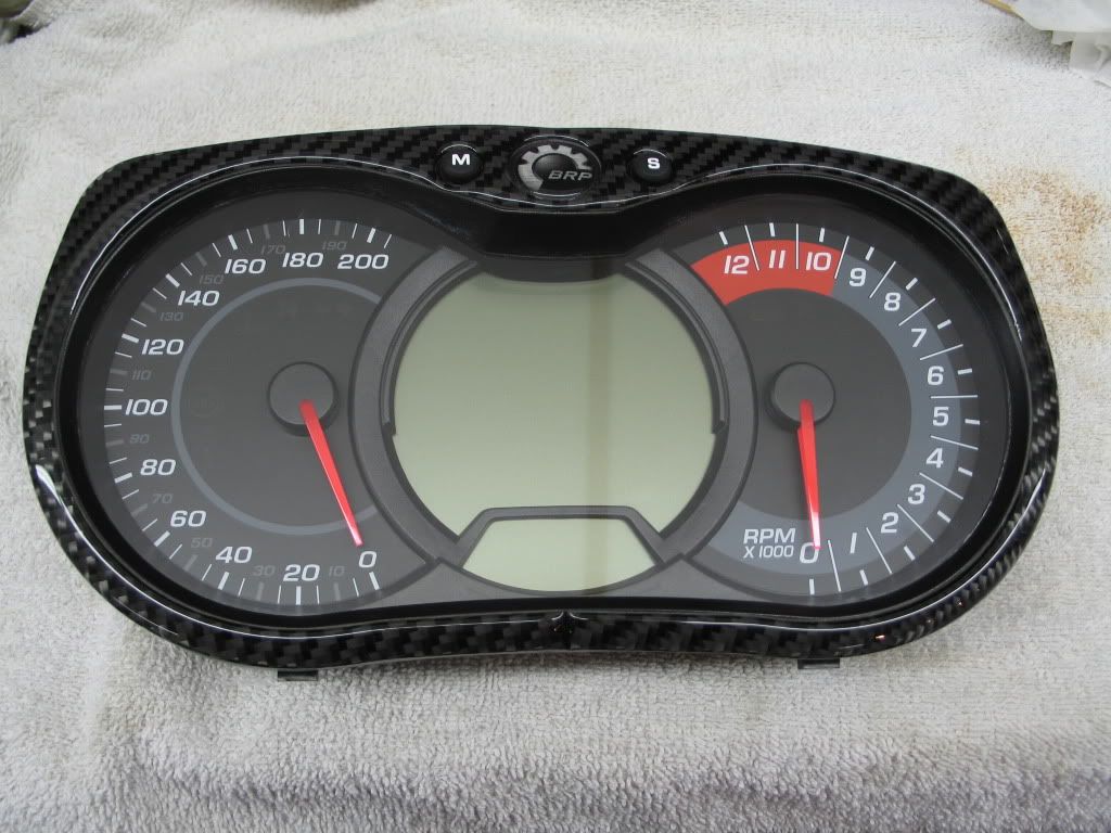
If you try to adhere the right section from the top, the two lower halves may not join together and a gap may be present in the lower center of the display.
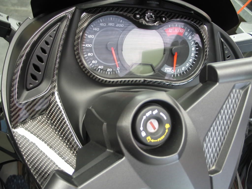
If done properly the results will be excellent:
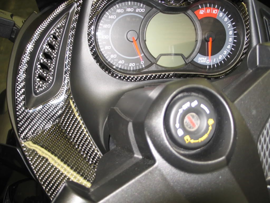
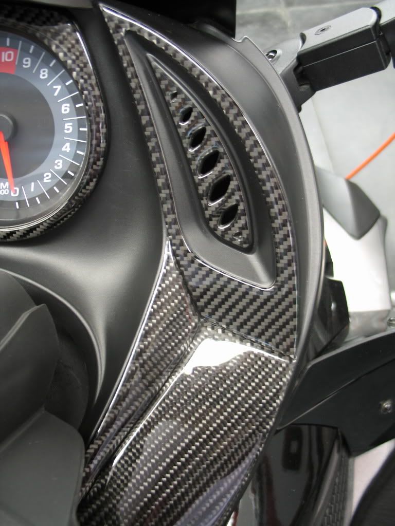
4612-11 Part-11, 4612-13 Part-13, 4612-19 Part-19:
These three parts combine to cover the left side of the dash console. They must be fitted together precisely for a proper fit.
Start by taking all three parts together and perform a test fit to see exactly how the parts align:
Move all the parts around until the best alignment is achieved. At that point remove Parts 13 and 19, leaving Part 11 in place.
Using a pencil, mark a line under the bottom of Part 11:
Adhere Part 11 first, using the pencil line as a guide. Do not try to adhere the part all at once, rather remove the protective backing only from the
bottom so you can still maintain alignment of the top without yet adhering it. Align and adhere the bottom only with the pencil mark and then,
working toward the top, gradually remove the remaining backing while carefully aligning the part.
With Part 11 now adhered in place, once again test fit Parts 13 and 19.
When the best alignment is achieved, remove Part 19 and mark a pencil line along the right side of Part 13:
Remove only the upper protective backing of Part 13 and align it with the lower end of Part 11, then gradually remove the backing while carefully
aligning it to the pencil mark. With Part 13 now adhered, carefully install Part 19:
Repeat this procedure for the equivalent right side parts (Parts 12, 14, and 20):
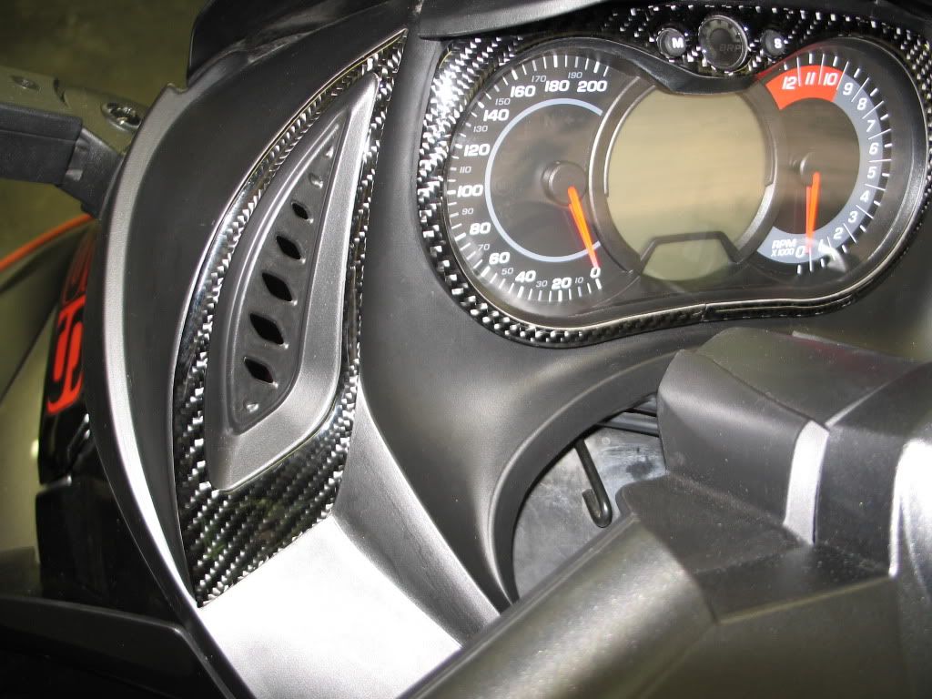
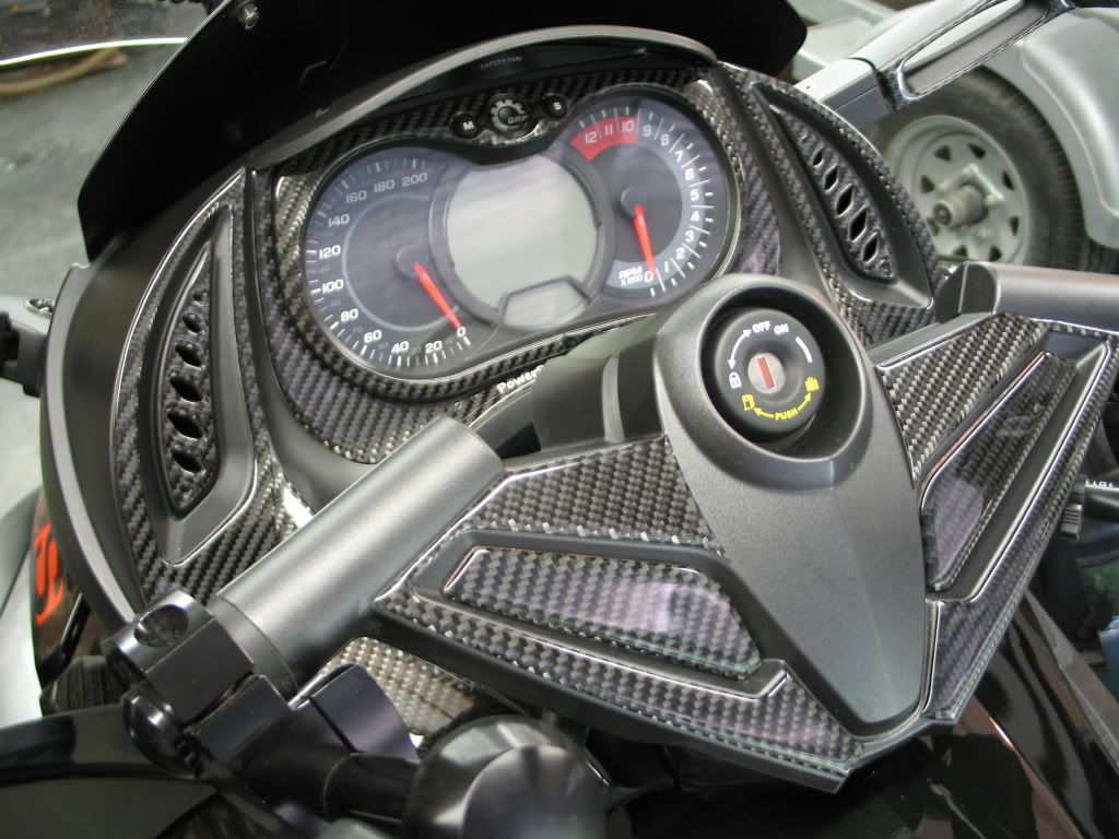
4612-07 Part-7:
When preparing the surface for Part-7, use care not to apply 3M adhesive promoter to any section of the dash that will not be covered by the part.
Test fit Part-7. When the best alignment is achieved mark a pencil line around the bottom of the part. Remove the backing from the lower half only
and carefully adhere it aligning to the pencil mark while holding the top half in place.
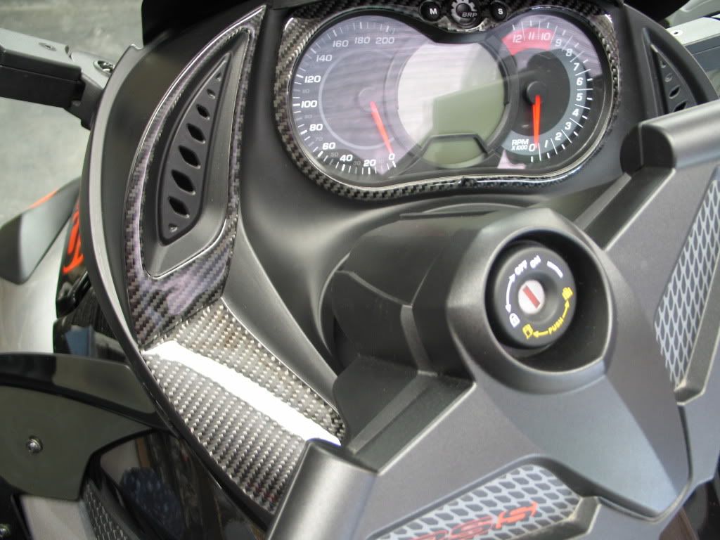
Now remove the upper half of the backing and adhere the top of the part in position:
Repeat this procedure for Part-8. Follow a similar procedure for Part-6:
The remaining parts can be installed after a test alignment without difficulty.
Last edited by pro10is; 06-21-2012 at 09:40 PM.
-
You got yours already? I was on the first list and never recieved a paypal invoice. Whats up?
-
 Originally Posted by wickeddose

You got yours already? I was on the first list and never recieved a paypal invoice. Whats up?
Check the list. I was the first person on the list, you are the eighth. Pete used the list to see if anyone would be willing to do a test fitting, I was the first to respond to purchase a kit so he called me and I accepted. Pete wanted to make sure the test kit was perfect before he sold the production kits to everyone else. Now that the test is complete I'm sure you'll be getting yours very soon. Contact Pete for conformation.
http://www.spyderlovers.com/forums/s...-Now-Available
-
Oh, I got you. Thanks man
-
man that looks good. If I had the extra $$$ right now id be totally getting that .
-
-
Man that looks sweet whats the cost of the kit i may have missed it some wheres else?
Thanks Mike
 Posting Permissions
- You may not post new threads
- You may not post replies
- You may not post attachments
- You may not edit your posts
-
Forum Rules
|


 Reply With Quote