Results 1 to 22 of 22
  1. #1
    Doc - Riverside
    Guest

    Default Adding Electric Front Trunk Release and PowerLet outlet 2014 and 2015 RT's

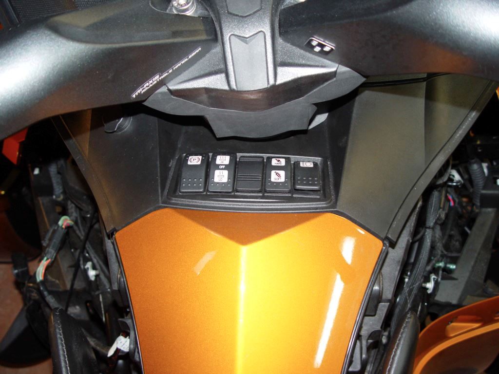
    This is how I installed the Electric Frunk release on my 2014 RT. I found that the wiring harness is still intact but is missing parts. The switches used on the console are Contura Style. One could try to buy the switch from BRP at a cost of $60.00 which has a blue instead of orange light and replace the parking brake switch to have the Frunk release function back in the original location. Going this route you still need the actuator, mounting hardware and connector parts. Next option is to purchase the $100 kit option that moves the switch option to the Fog light position switch. Besides cost I don't like the idea of turning the fog lights off every time I want to open the Frunk. My Fog lights are always on.

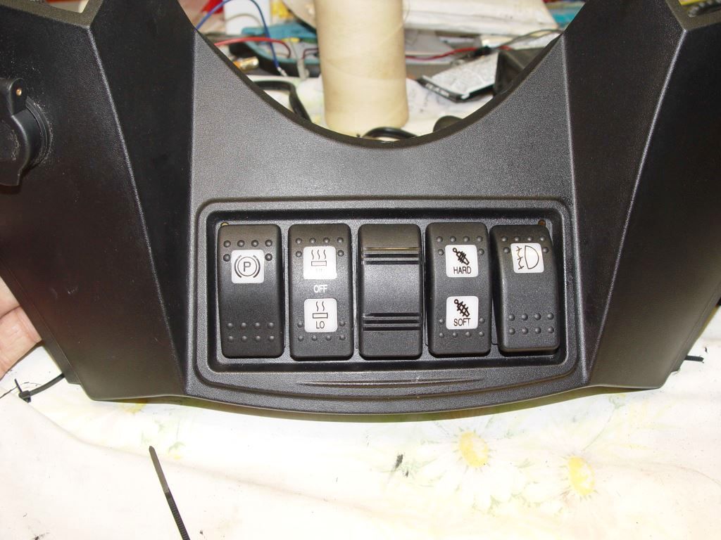
    The option I went with is to install a Double Pole - Double Throw (momentary on) switch in the center position of the switch console. Rear of switch is to open the Frunk ( original design) and the front of the switch is to operate the Garage door opener.

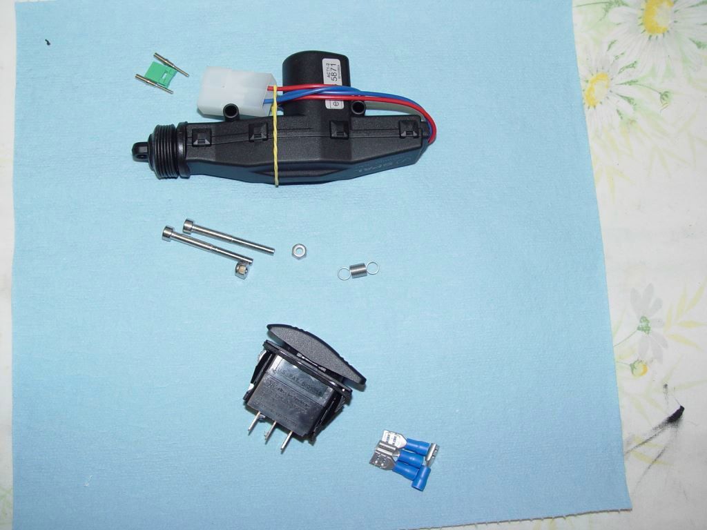
    Here is a picture of the parts needed


    Top left is the two male pins and green wedge block you need for the connector you install on the actuator. The pins are a crimp style but can be soldered.
    Pins from http://www.deutschconnector.com/products/deutsch_pins_and_sockets/deutsch_dt_pins_and_sockets/0460-202-16141/

    wedge from

    http://www.deutschconnector.com/prod...ent_parts/W2P/

    For the Actuator Google " SPAL 37000003 ".
    For the Switch Google " Blue Sea Systems Contura 8290 switch "
    Spring can be ordered from ( WWW.McMaster.com ) Part number 9065K194
    The bolts and lock nuts can be ordered from Bolt Depot


    m4 x 40 bolt
    https://www.boltdepot.com/Product-De...x?product=6402

    m4 lock nut
    https://www.boltdepot.com/Product-De...x?product=4793


    You will also need 1/4 inch male and female spade lugs, tie wraps and heat shrink.

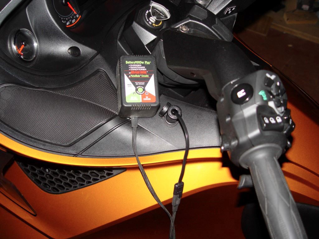
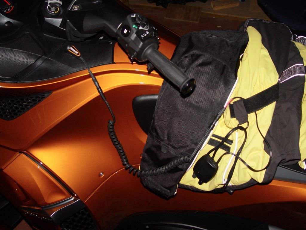
    Google " Powerlet PSO-007 " if you want to install +12vdc power on the left side of the glove box for plugging in a battery maintainer of heated cloths.

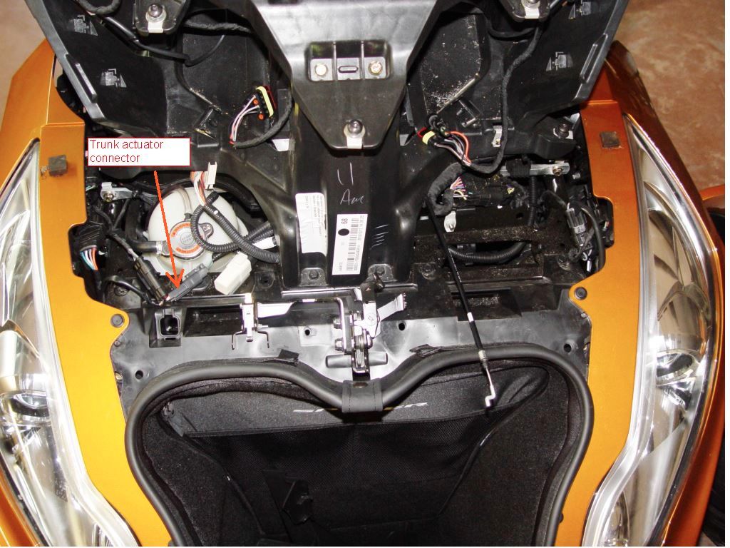
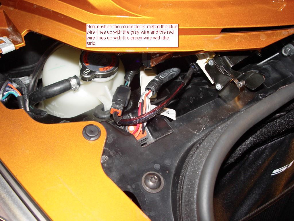
    To get started you need to remove both mirror, lower wind deflectors, both upper side panels, Headlight trim and the two triangle pieces of plastic in the frunk. Locate and remove the connector plug as shown. This will be installed on the actuator.


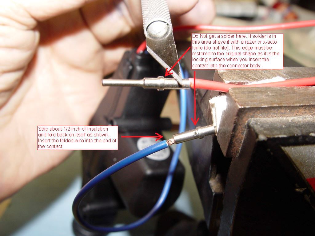
    Now we will install the pins on the actuator. Cut the white nylon connector off the actuator and discard. At the plug you removed from the trunk actuator connector remove the two white pins and the reddish rubber gasket. Install the red gasket on the red and blue wire of the actuator. The contacts can be crimped on if you have the $300 crimper or you can solder them on the wire. Do Not try to do the crimp with pliers. It will deform the contact so it won't seat in the connector body. It is critical that you use just enough solder to do the job. The lip shown in the picture must remain as close to original shape as possible for the contact to lock into the connector. When soldering the pin use heavy paper between the pin and the clamping device. This prevents the device from becoming a heat sink while you are trying to solder.


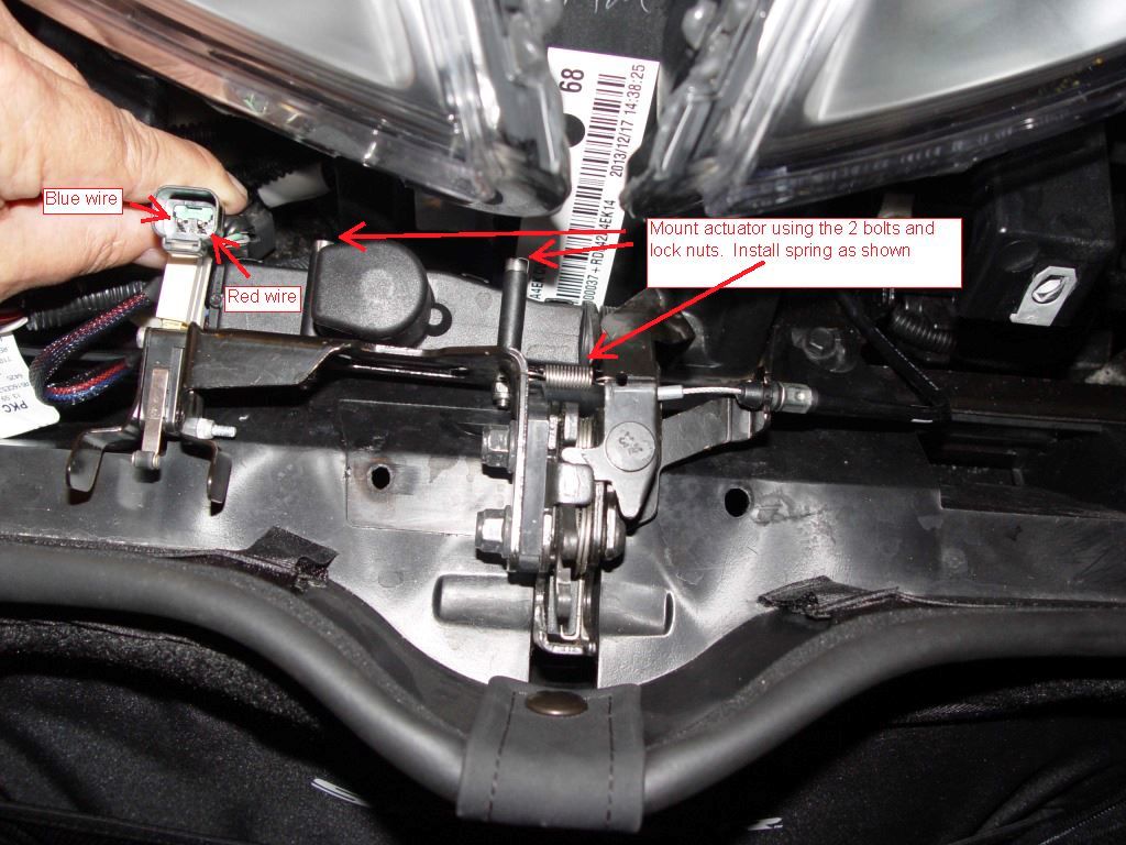
    Now you are ready to put the pins into the connector body. Use the below two pictures to ensure the pins are located correctly. The red wire should line up with the green wire when you mate the two connector. With the pins inserted into the connector install the green wedge as shown and firmly seat. Slide the red gasket into the back the back of the connector. Now mount the actuator and spring.


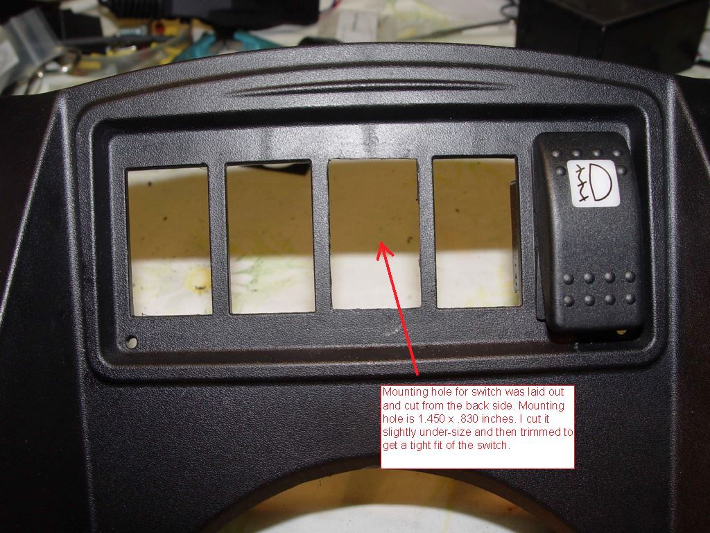
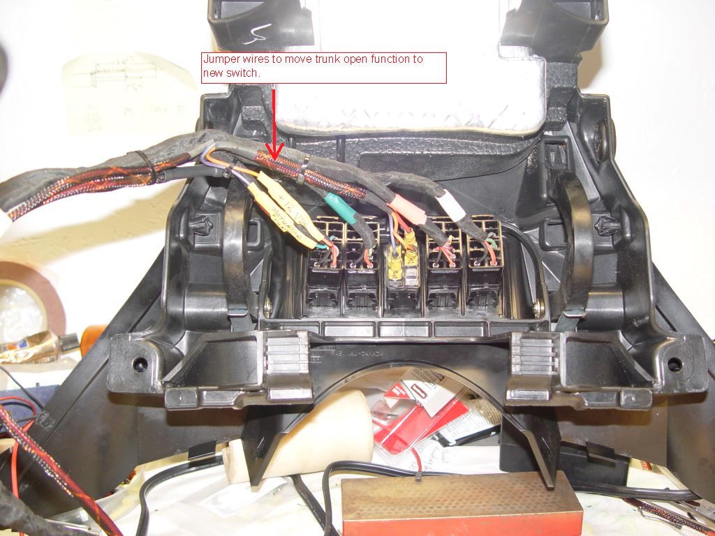
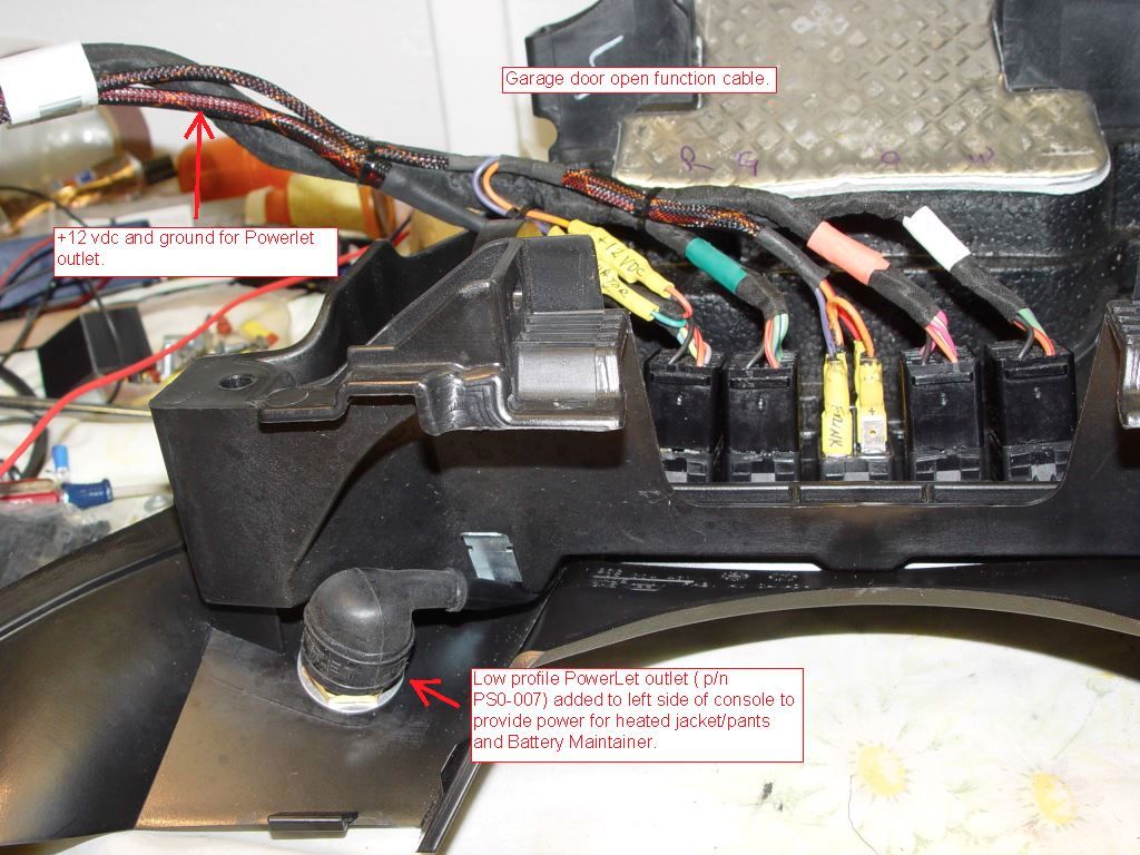
    To install the new switch and Powerlet outlet remove the Glove box. Remove plastic rivet's and plastic parts until you get to the switches and harness. Disconnect all the switches and remove the harness. Remove the switches. Mark up the center for the new switch mounting hole and cut out. It is best to be slightly under size on the hole and then carefully open it up to just fit the new switch.


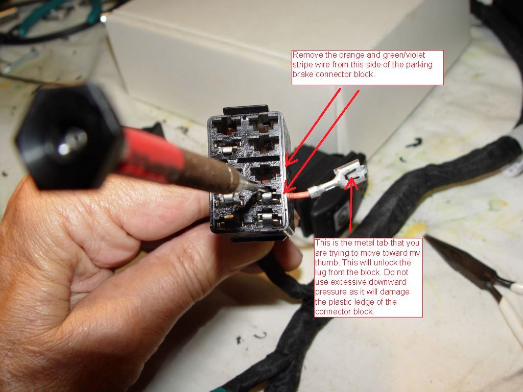
    Next step is to remove the two female spade contacts from the switch connector for the parking brake. You want to remove the two wires as shown. Orange is +12vdc switched power and the green/violet goes to the red wire on the actuator.


    Reinstall the switches and reconnect the harness to the switches. Mount the Powerlet outlet as shown.


    Using the male and female spade lugs, fabricate a new wire harness to connect up the power and actuator signal to the new switch. Cover the new harness connection to the orange and green/violet wire with heat shrink. The orange wire was connected to two center posts of the switch because my garage door opener requires 12vdc to operate. The left center lug of the new switch is the only one that needs the orange wire for the actuator to work. What you use the second option of the switch is your choice. I wired the rear of the switch to open the Frunk.


    Powerlet wires also had extra red and black wire added to extend the wire for hookup at the alternator.


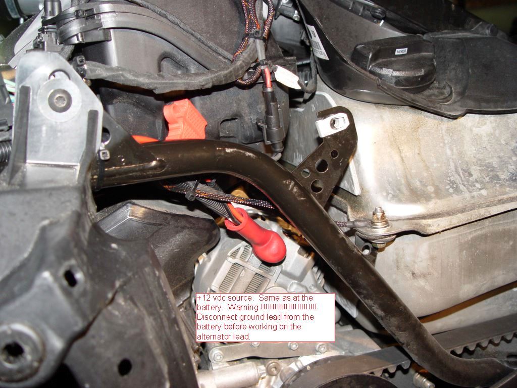
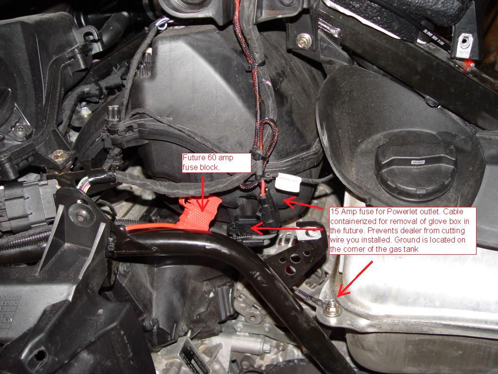
    Picture showing how +12vdc is picked up off the alternator post. Warning !!!!!!!!!!!!!! disconnect negative lead on battery prior to working on alternator post. I made up two inline fused connections. One is for a yet to be added fuse block (Red Fuse ) and the black one is for the Powerlet outlet ( fused at 15amps) .


    Final product


  2. #2
    Active Member hognut's Avatar
    Join Date
    Sep 2014
    Location
    Grants Pass, OR
    Posts
    76
    Spyder Garage
    0

    Thumbs up Great how to

    Thank you for the very detailed "how to", you put in a lot of work to help others. I will put this on my to-do list

  3. #3
    Very Active Member ThreeWheels's Avatar
    Join Date
    Feb 2010
    Location
    Danbury Connecticut
    Posts
    3,479
    Spyder Garage
    0

    Default

    Nice job Doc. Thanks for posting.
    I want to ask you about the fog lights. I'll pm you.
    If it ain't broke, don't break it.
    IBA #47122
    2020 RT Limited Asphalt Grey

  4. #4
    Very Active Member Chupaca's Avatar
    Join Date
    Oct 2012
    Location
    San Diego, CA.
    Posts
    31,097
    Spyder Garage
    1

    Default Nicely done..!!

    Wish the manuals out there were this detailed...thanks..!!
    Gene and Ilana De Laney
    Mt. Helix, California

    ​2012 RS sm5
    2012 RS sm5 , 998cc V-Twin 106hp DIY brake and park brake Classic Black

  5. #5
    Very Active Member
    Join Date
    Sep 2010
    Location
    Not Here
    Posts
    92,464
    Spyder Garage
    1
    2010 RT A&C, RT-L, RT-L , Orbital Blue, Cognac, Jet Black

  6. #6
    Very Active Member cuznjohn's Avatar
    Join Date
    Jun 2013
    Location
    queens ny
    Posts
    9,280
    Spyder Garage
    0

    Default

    trice has a frunk opener for the bikes for 69 dollars, when i ordered some lights i also ordered the opener and for some reason they refunded me the money for the opener w/o saying if they were out of stock or if it didn't work on the rt or the 2014
    NO BIKE AT THIS TIME

  7. #7
    Doc - Riverside
    Guest

    Default

    Quote Originally Posted by cuznjohn View Post
    trice has a frunk opener for the bikes for 69 dollars, when i ordered some lights i also ordered the opener and for some reason they refunded me the money for the opener w/o saying if they were out of stock or if it didn't work on the rt or the 2014
    I shopped around for the parts and what you see on the blue towel cost about $40 plus shipping and it works. The harness is there you just need to add the missing parts. This should work on the 2015 Models also.

  8. #8
    Very Active Member BikerDoc's Avatar
    Join Date
    Sep 2010
    Location
    Clermont, Florida
    Posts
    2,600
    Spyder Garage
    0

    Default

    Impressive
    220,000 Mile Spyder Ryder, IBA Premier member #59352, Saddlesore 1000 (11), Bun Burner 1500 (3), Saddlesore 2000 (2), Bun Burner Gold, MILEEATER SILVER

  9. #9
    Registered Users
    Join Date
    Aug 2014
    Location
    wv
    Posts
    268
    Spyder Garage
    0

    Default

    Added this to my ST the other month, bt bought the kit.
    It's been a great addition... stopping to add something to the fruk after you just started the bike. Or needed to grab your rain gear mid way up the mountain, not wanting to kill the engine .

  10. #10
    Very Active Member bluestratos's Avatar
    Join Date
    Jun 2011
    Location
    Lynden, WA
    Posts
    1,835
    Spyder Garage
    0

    Default

    I did the same thing for the frunk opener with one exception, I ran the wires to a remote momentary contact switch so I can open the frunk without the key and since I have the com set I already had the middle switch location filled. Total coast was $15 since but I already had the momentary contact switch.

  11. #11
    Very Active Member billybovine's Avatar
    Join Date
    Jul 2011
    Location
    Mitchell, Ontario, Canada
    Posts
    6,264
    Spyder Garage
    0

    Default

    Quote Originally Posted by zamfield View Post
    Added this to my ST the other month, bt bought the kit.
    It's been a great addition... stopping to add something to the fruk after you just started the bike. Or needed to grab your rain gear mid way up the mountain, not wanting to kill the engine .
    You don't have to kill the engine to open the trunk or the seat with the key. Just push down and turn. Engine not affected.

    2018 F3 LIMITED

  12. #12
    Registered Users
    Join Date
    Aug 2014
    Location
    wv
    Posts
    268
    Spyder Garage
    0

    Default

    Quote Originally Posted by billybovine View Post
    You don't have to kill the engine to open the trunk or the seat with the key. Just push down and turn. Engine not affected.
    Well, what do ya know!

    I like momentary switch anyway!

  13. #13
    Active Member Biggdogg22's Avatar
    Join Date
    May 2013
    Location
    Chesapeake, Virginia
    Posts
    70
    Spyder Garage
    0

    Default

    I tried to locate the trunk connector. Did you have to pull it out from behind the coolent reservoir? Was it connected to something?


    Thanks

    Quote Originally Posted by Doc - Riverside View Post
    This is how I installed the Electric Frunk release on my 2014 RT. I found that the wiring harness is still intact but is missing parts. The switches used on the console are Contura Style. One could try to buy the switch from BRP at a cost of $60.00 which has a blue instead of orange light and replace the parking brake switch to have the Frunk release function back in the original location. Going this route you still need the actuator, mounting hardware and connector parts. Next option is to purchase the $100 kit option that moves the switch option to the Fog light position switch. Besides cost I don't like the idea of turning the fog lights off every time I want to open the Frunk. My Fog lights are always on.

    The option I went with is to install a Double Pole - Double Throw (momentary on) switch in the center position of the switch console. Rear of switch is to open the Frunk ( original design) and the front of the switch is to operate the Garage door opener.

    Here is a picture of the parts needed


    Top left is the two male pins and green wedge block you need for the connector you install on the actuator. The pins are a crimp style but can be soldered.
    Pins from http://www.deutschconnector.com/products/deutsch_pins_and_sockets/deutsch_dt_pins_and_sockets/0460-202-16141/

    wedge from

    http://www.deutschconnector.com/prod...ent_parts/W2P/

    For the Actuator Google " SPAL 37000003 ".
    For the Switch Google " Blue Sea Systems Contura 8290 switch "
    Spring can be ordered from ( WWW.McMaster.com ) Part number 9065K194
    The bolts and lock nuts can be ordered from Bolt Depot


    m4 x 40 bolt
    https://www.boltdepot.com/Product-De...x?product=6402

    m4 lock nut
    https://www.boltdepot.com/Product-De...x?product=4793


    You will also need 1/4 inch male and female spade lugs, tie wraps and heat shrink.

    Google " Powerlet PSO-007 " if you want to install +12vdc power on the left side of the glove box for plugging in a battery maintainer of heated cloths.

    To get started you need to remove both mirror, lower wind deflectors, both upper side panels, Headlight trim and the two triangle pieces of plastic in the frunk. Locate and remove the connector plug as shown. This will be installed on the actuator.


    Now we will install the pins on the actuator. Cut the white nylon connector off the actuator and discard. At the plug you removed from the trunk actuator connector remove the two white pins and the reddish rubber gasket. Install the red gasket on the red and blue wire of the actuator. The contacts can be crimped on if you have the $300 crimper or you can solder them on the wire. Do Not try to do the crimp with pliers. It will deform the contact so it won't seat in the connector body. It is critical that you use just enough solder to do the job. The lip shown in the picture must remain as close to original shape as possible for the contact to lock into the connector. When soldering the pin use heavy paper between the pin and the clamping device. This prevents the device from becoming a heat sink while you are trying to solder.


    Now you are ready to put the pins into the connector body. Use the below two pictures to ensure the pins are located correctly. The red wire should line up with the green wire when you mate the two connector. With the pins inserted into the connector install the green wedge as shown and firmly seat. Slide the red gasket into the back the back of the connector. Now mount the actuator and spring.


    To install the new switch and Powerlet outlet remove the Glove box. Remove plastic rivet's and plastic parts until you get to the switches and harness. Disconnect all the switches and remove the harness. Remove the switches. Mark up the center for the new switch mounting hole and cut out. It is best to be slightly under size on the hole and then carefully open it up to just fit the new switch.


    Next step is to remove the two female spade contacts from the switch connector for the parking brake. You want to remove the two wires as shown. Orange is +12vdc switched power and the green/violet goes to the red wire on the actuator.


    Reinstall the switches and reconnect the harness to the switches. Mount the Powerlet outlet as shown.


    Using the male and female spade lugs, fabricate a new wire harness to connect up the power and actuator signal to the new switch. Cover the new harness connection to the orange and green/violet wire with heat shrink. The orange wire was connected to two center posts of the switch because my garage door opener requires 12vdc to operate. The left center lug of the new switch is the only one that needs the orange wire for the actuator to work. What you use the second option of the switch is your choice. I wired the rear of the switch to open the Frunk.


    Powerlet wires also had extra red and black wire added to extend the wire for hookup at the alternator.


    Picture showing how +12vdc is picked up off the alternator post. Warning !!!!!!!!!!!!!! disconnect negative lead on battery prior to working on alternator post. I made up two inline fused connections. One is for a yet to be added fuse block (Red Fuse ) and the black one is for the Powerlet outlet ( fused at 15amps) .


    Final product


  14. #14
    Doc - Riverside
    Guest

    Default

    Quote Originally Posted by Biggdogg22 View Post
    I tried to locate the trunk connector. Did you have to pull it out from behind the coolent reservoir? Was it connected to something?


    Thanks
    It is tucked in the corner to the right of the coolant tank. You should see the two white dots. That is the male connector you remove to install the actuator pins. Its hid there somewhere. Follow the BUDS connector cable back.

  15. #15
    Active Member Biggdogg22's Avatar
    Join Date
    May 2013
    Location
    Chesapeake, Virginia
    Posts
    70
    Spyder Garage
    0

    Default

    Got it all hooked up like you stated. However, I have no power at the connector. Did you leave out a step.? Is there a fuse that need to be place, etc

    Reg
    Quote Originally Posted by Doc - Riverside View Post
    It is tucked in the corner to the right of the coolant tank. You should see the two white dots. That is the male connector you remove to install the actuator pins. Its hid there somewhere. Follow the BUDS connector cable back.

  16. #16
    Doc - Riverside
    Guest

    Default

    Quote Originally Posted by Biggdogg22 View Post
    Got it all hooked up like you stated. However, I have no power at the connector. Did you leave out a step.? Is there a fuse that need to be place, etc

    Reg
    Orange wire from the parking brake switch is the 12vdc source. The 12vdc is there when you turn the key on. You can call me at 912-496-3015
    Doc
    Last edited by Doc - Riverside; 10-26-2014 at 01:47 AM.

  17. #17
    Very Active Member Purple Guy's Avatar
    Join Date
    May 2013
    Location
    Edmonton Alberta, Canada
    Posts
    1,874
    Spyder Garage
    1

    Default

    Wow! Thanks for the extra effort in your step by step tutorial!
    2014 RT-Ltd , Cognac

  18. #18
    Active Member
    Join Date
    Sep 2014
    Location
    East Texas
    Posts
    470
    Spyder Garage
    0

    Default Man, you are amazing

    Thank you for the amazing pictures to share your engineering abilities to the rest of us. Buddy, I bow to you and this is something that I ordinarily would save for God himself.

  19. #19
    Registered Users Andy Cserny's Avatar
    Join Date
    Nov 2011
    Location
    Raleigh Illinois
    Posts
    132
    Spyder Garage
    0

    Default powerlet hookup

    Great writeup and very detailed. I Just bought a 2014 RT and have just started farkling and I will definitely bookmark this very detailed and informative HOW TO. I do have aquestion: where did you find the low profile Powerlet connectors?? You gave the part #, but not the source
    Thanks
    Andy

  20. #20
    Doc - Riverside
    Guest

    Default

    Quote Originally Posted by Andy Cserny View Post
    Great writeup and very detailed. I Just bought a 2014 RT and have just started farkling and I will definitely bookmark this very detailed and informative HOW TO. I do have aquestion: where did you find the low profile Powerlet connectors?? You gave the part #, but not the source
    Thanks
    Andy
    www.powerlet.com

  21. #21
    Active Member
    Join Date
    Dec 2014
    Location
    Central, Florida
    Posts
    41
    Spyder Garage
    0

    Default Kool Stuff...

    Quote Originally Posted by Doc - Riverside View Post
    This is how I installed the Electric Frunk release on my 2014 RT. I found that the wiring harness is still intact but is missing parts. The switches used on the console are Contura Style. One could try to buy the switch from BRP at a cost of $60.00 which has a blue instead of orange light and replace the parking brake switch to have the Frunk release function back in the original location. Going this route you still need the actuator, mounting hardware and connector parts. Next option is to purchase the $100 kit option that moves the switch option to the Fog light position switch. Besides cost I don't like the idea of turning the fog lights off every time I want to open the Frunk. My Fog lights are always on.

    The option I went with is to install a Double Pole - Double Throw (momentary on) switch in the center position of the switch console. Rear of switch is to open the Frunk ( original design) and the front of the switch is to operate the Garage door opener.

    Here is a picture of the parts needed


    Top left is the two male pins and green wedge block you need for the connector you install on the actuator. The pins are a crimp style but can be soldered.
    Pins from http://www.deutschconnector.com/products/deutsch_pins_and_sockets/deutsch_dt_pins_and_sockets/0460-202-16141/

    wedge from

    http://www.deutschconnector.com/prod...ent_parts/W2P/

    For the Actuator Google " SPAL 37000003 ".
    For the Switch Google " Blue Sea Systems Contura 8290 switch "
    Spring can be ordered from ( WWW.McMaster.com ) Part number 9065K194
    The bolts and lock nuts can be ordered from Bolt Depot


    m4 x 40 bolt
    https://www.boltdepot.com/Product-De...x?product=6402

    m4 lock nut
    https://www.boltdepot.com/Product-De...x?product=4793


    You will also need 1/4 inch male and female spade lugs, tie wraps and heat shrink.

    Google " Powerlet PSO-007 " if you want to install +12vdc power on the left side of the glove box for plugging in a battery maintainer of heated cloths.

    To get started you need to remove both mirror, lower wind deflectors, both upper side panels, Headlight trim and the two triangle pieces of plastic in the frunk. Locate and remove the connector plug as shown. This will be installed on the actuator.


    Now we will install the pins on the actuator. Cut the white nylon connector off the actuator and discard. At the plug you removed from the trunk actuator connector remove the two white pins and the reddish rubber gasket. Install the red gasket on the red and blue wire of the actuator. The contacts can be crimped on if you have the $300 crimper or you can solder them on the wire. Do Not try to do the crimp with pliers. It will deform the contact so it won't seat in the connector body. It is critical that you use just enough solder to do the job. The lip shown in the picture must remain as close to original shape as possible for the contact to lock into the connector. When soldering the pin use heavy paper between the pin and the clamping device. This prevents the device from becoming a heat sink while you are trying to solder.


    Now you are ready to put the pins into the connector body. Use the below two pictures to ensure the pins are located correctly. The red wire should line up with the green wire when you mate the two connector. With the pins inserted into the connector install the green wedge as shown and firmly seat. Slide the red gasket into the back the back of the connector. Now mount the actuator and spring.


    To install the new switch and Powerlet outlet remove the Glove box. Remove plastic rivet's and plastic parts until you get to the switches and harness. Disconnect all the switches and remove the harness. Remove the switches. Mark up the center for the new switch mounting hole and cut out. It is best to be slightly under size on the hole and then carefully open it up to just fit the new switch.


    Next step is to remove the two female spade contacts from the switch connector for the parking brake. You want to remove the two wires as shown. Orange is +12vdc switched power and the green/violet goes to the red wire on the actuator.


    Reinstall the switches and reconnect the harness to the switches. Mount the Powerlet outlet as shown.


    Using the male and female spade lugs, fabricate a new wire harness to connect up the power and actuator signal to the new switch. Cover the new harness connection to the orange and green/violet wire with heat shrink. The orange wire was connected to two center posts of the switch because my garage door opener requires 12vdc to operate. The left center lug of the new switch is the only one that needs the orange wire for the actuator to work. What you use the second option of the switch is your choice. I wired the rear of the switch to open the Frunk.


    Powerlet wires also had extra red and black wire added to extend the wire for hookup at the alternator.


    Picture showing how +12vdc is picked up off the alternator post. Warning !!!!!!!!!!!!!! disconnect negative lead on battery prior to working on alternator post. I made up two inline fused connections. One is for a yet to be added fuse block (Red Fuse ) and the black one is for the Powerlet outlet ( fused at 15amps) .


    Final product


    Hi I'm a "newbie" & was asking about adding an power outlet up front to charge my phone or for other accessories & you've answered the question with this post. Thanks...
    Great pics & notes on How To Do This....& I have a question, would you considered installing PDM-60 (http://pdm60.com/) power distribution module? I realize that they are not cheap but as I am planning to add more things that require a power source I was considering this as a means for powering up such devices. What do you think?

    Nelson

  22. #22
    Active Member Doc - Riverside's Avatar
    Join Date
    Jan 2010
    Location
    USA Folkston,Ga
    Posts
    249
    Spyder Garage
    0

    Default

    Quote Originally Posted by arecibo50 View Post
    Hi I'm a "newbie" & was asking about adding an power outlet up front to charge my phone or for other accessories & you've answered the question with this post. Thanks...
    Great pics & notes on How To Do This....& I have a question, would you considered installing PDM-60 (http://pdm60.com/) power distribution module? I realize that they are not cheap but as I am planning to add more things that require a power source I was considering this as a means for powering up such devices. What do you think?

    Nelson
    I have one but haven't installed it yet. I like the the different options that you can program each output to. I plan on mounting it somewhere around the horn area and picking up the power off the alternator lug. You have to make sure that you pull the negative lead on the battery before doing this. If you don't have a 2014 RT you have to go to the battery to get power.

Posting Permissions

  • You may not post new threads
  • You may not post replies
  • You may not post attachments
  • You may not edit your posts
  •