|
-
 Heated grip help Heated grip help
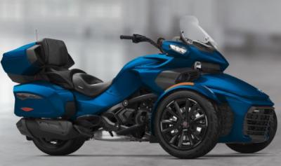
PO removed the passenger heated grips and replaced with non heated arm rests. Since the f3 limited 2018 does not have a 12 recp. in top case i wanted to use this power for that. I found two plugs under pass. seat , they must be for grips. With engine running and gripheater sw depressed the right side one has 12 v but the left side nothing.
WHY would this be? Also the wirewires look a little light for using anything with a heavy current draw.
-

The 12v under the seat is one of three accessory circuits available to plug in a variety of gizmos or contraptions.
Heated anything draws a lot of amps so run a direct line to the battery and add a fuse so you don't fry something.
The Spyder is VERY unfriendly in any altercations to its electrical system....so go directly off the battery for high demand items.
 Originally Posted by AsphaltEagle

PO removed the passenger heated grips and replaced with non heated arm rests. Since the f3 limited 2018 does not have a 12 recp. in top case i wanted to use this power for that. I found two plugs under pass. seat , they must be for grips. With engine running and gripheater sw depressed the right side one has 12 v but the left side nothing.
WHY would this be? Also the wirewires look a little light for using anything with a heavy current draw.
-
 heated grips heated grips
Ok, there is a wire under passenger seat labeled " owner accessory ". this in not the wires I question. there are Two purple connectors, one on each side, they must be for connection to the heated grip handles. Which my bike does not have as the PO removed them. when I check for voltage on these two connectors with motor on and heater sw depressed I get 12 volts on the right one but none on the left one. My question is why no voltage on the left connector? Also the wires are fairly small diameter. since the fuse is rated at 10 amps for this circuit why the small wires. 10 amp fuse makes since for the heated grips but I would expect larger wires.
I am trying to avoid pulling larger wires from battery all the way to top case, when I have a switched ( heater grip switch) circuit already there. suposedly a 10 amp circuit.
-

Fuse?
Did you check continuity?
Did you check amps at the Switch?
This is why I wire accessories myself. I keep it simple cause simple works.
 Originally Posted by AsphaltEagle

Ok, there is a wire under passenger seat labeled " owner accessory ". this in not the wires I question. there are Two purple connectors, one on each side, they must be for connection to the heated grip handles. Which my bike does not have as the PO removed them. when I check for voltage on these two connectors with motor on and heater sw depressed I get 12 volts on the right one but none on the left one. My question is why no voltage on the left connector? Also the wires are fairly small diameter. since the fuse is rated at 10 amps for this circuit why the small wires. 10 amp fuse makes since for the heated grips but I would expect larger wires.
I am trying to avoid pulling larger wires from battery all the way to top case, when I have a switched ( heater grip switch) circuit already there. suposedly a 10 amp circuit.
-
 Heated grip circuit Heated grip circuit
Only one power source and one switch feeds both sides. Since one side has power the fuse has to be good. I followed diagram from heated grip to terminals on c1c1, then from switch to terminals on c1c2. But can't seem to find diagram for circuit in between. Gotta be there somewhere.
-
Very Active Member


The rear heated grip plugs, according to the wiring diagram. The switched 12V should be a light green with a white tracer. Not purple. Are you sure you have the right plugs?
I think that CIC1 and CIC2 are the same connector. Looks like a mistake on the wiring diagram. I have looked at this before.
The accessory circuit should be attached to the USB plugs in the top case. If you want a 12V power socket instead. Why not just pop out the usb plug and install a 12V socket?
Last edited by billybovine; 07-05-2018 at 03:50 PM.

2018 F3 LIMITED
-

Billy, i want to have both available. The purple i was referring to was the color of the plug. At least thats what it looks like to me. I wasn't sure if c1c1 and c1c2 was the sane or maybe a harness between them.
I'll probably cut the plug off the on that has voltage on and use it. Still don't know why the other doesn't have voltage, but haven't checked any further.
-
Very Active Member


If you want both a USB and 12V socket just split the accessory circuit. It's got 10 amp available.

2018 F3 LIMITED
-
Ozzie Ozzie Ozzie


Concerning the 'why does the right side have switched 12V power & the left side doesn't' question, IF those 'purple plugs' do actually have anything to do with the heated grips, could it be that the right side provides power to the circuit & the left is there to enable the completion of that circuit?? After all, when it's all connected & working, it's meant to be a circuit with continuity, which at the most basic level implies power going from the battery post at one end & somehow completing the circuit back to the other battery post at the other end....  And maybe the lightweight wires are just meant to trigger a relay providing power to the heated grips thru a heavier & now removed or used elsewhere wire?? Yeah, I know that the circuit could be grounded thru the frame, but since those of us without a wiring diagram &/or the Spyder in front of us don't know/can't see exactly what has been removed or which plugs are those concerned, it is really just me pondering....... sorry if it doesn't help, but you did ask..... And maybe the lightweight wires are just meant to trigger a relay providing power to the heated grips thru a heavier & now removed or used elsewhere wire?? Yeah, I know that the circuit could be grounded thru the frame, but since those of us without a wiring diagram &/or the Spyder in front of us don't know/can't see exactly what has been removed or which plugs are those concerned, it is really just me pondering....... sorry if it doesn't help, but you did ask..... 
Last edited by Peter Aawen; 07-05-2018 at 09:01 PM.
2013 RT Ltd Pearl White
Ryde More, Worry Less!
-
Very Active Member


 Originally Posted by Peter Aawen

Concerning the ' why does the right side have switched 12V power & the left side doesn't' question, IF those 'purple plugs' do actually have anything to do with the heated grips, could it be that the right side provides power to the circuit & the left is there to enable the completion of that circuit?? After all, when it's all connected & working, it's meant to be a circuit with continuity, which at the most basic level implies power going from the battery post at one end & somehow completing the circuit back to the other battery post at the other end....  And maybe the lightweight wires are just meant to trigger a relay providing power to the heated grips thru a heavier & now removed or used elsewhere wire?? Yeah, I know that the circuit could be grounded thru the frame, but since those of us without a wiring diagram &/or the Spyder in front of us don't know/can't see exactly what has been removed or which plugs are those concerned, it is really just me pondering....... sorry if it doesn't help, but you did ask..... 
Nope. The rear grip heaters are connected in parallel not series. The common 12V wire comes from the rear grip heater relay in the fuse box. To the rear harness. Then splits from one into 2 wires at a junction in the rear harness. I guess it is possible that the junction is bad. But I seriously doubt it.

2018 F3 LIMITED
 Posting Permissions
- You may not post new threads
- You may not post replies
- You may not post attachments
- You may not edit your posts
-
Forum Rules
|


 Reply With Quote

 And maybe the lightweight wires are just meant to trigger a relay providing power to the heated grips thru a heavier & now removed or used elsewhere wire?? Yeah, I know that the circuit could be grounded thru the frame, but since those of us without a wiring diagram &/or the Spyder in front of us don't know/can't see exactly what has been removed or which plugs are those concerned, it is really just me pondering....... sorry if it doesn't help, but you did ask.....

